Scratch Jupiter II Original Design / Scratch Built
Scratch - Jupiter II {Scratch}
Contributed by Glenn Roth
| Manufacturer: | Scratch |
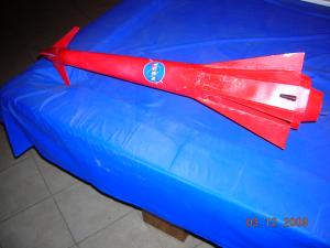
Brief:
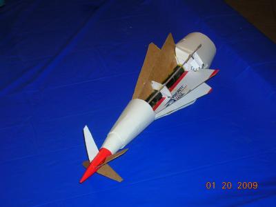
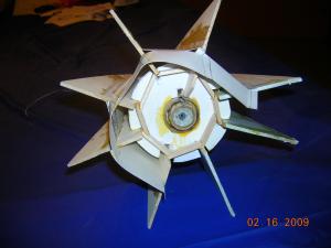
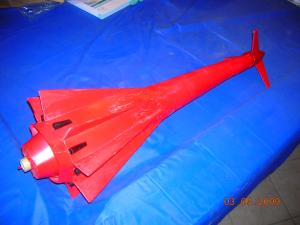
11 "Finned" rocket that can be launched on a single "E" or staged (D12-0, D12-3) with a parachute
recovery.
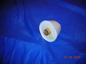
Prototype:
I built a protoype of my choice of rockets for the EMRR "Rockets of the Future." I choose to to do an 18mm
version first. I gathered some cardboard, posterboard, and second hand parts, etc. It would have been ten times harder
without the EMRR "Calculators", for shrouds, etc. I chose cardboard figuring, "If I can get this to fly
without a cad program, from the heaviest material, I surely will be able to build one in the 24 MM scale. Also,
cardboard a little easier to work with than "foamboard."
My 1st test flight was a disaster. (Remember, I have no software to determine where the CP & CG Is and if it will fly.) After giving it some thought, cut open nosecone and added some clay to move CG forward. Last Saturday flew it again and success! It only went 50 ft up but successfully deployed chute right before landing.
What I've learned is,"use the material in your prototype, that u intend to use on your final version." Mine did fly but, would have saved a lot of aggravation and speeded up the build. Also, Highly recommended building a prototype, especially in my case. My submission for the "rocket of the future" has 12 fins! Never came close to design such a complex rocket before.
Construction:
PARTS LIST:
- 24mm engine block
- 1 engine hooks
- 1 sheet of foam board, 20x30x1/4"
- 2 sheets of poster board, 20x30"
- 1 (priority mailing box)
- 2 BT-55's (15" long)
- 1 BT-55 coupler
- 18"x24mm Body tube for "engine Mounts"
- Shock cord; ¼"x 24+"
- 3, 4"x"36"x1/8 balsa sheets/basswood
- 1 "quest" egglofter nosecone
- 1 (18") parachute, & shroud line
- "non-hardening" clay
- (8) bic pen caps to "simulate 8 motors"
- 2 spent "D" engines
- Templates (will be loaded shortly)
Just wanted to interject for a moment. Hope you find this rocket as much of a challenge to build as I found to design it, without the help of any "Cad software." If anyone cares to "plug" these measurements into a cad program, I would be very curious as to the result. I did use EMRR "Calculators" for the shrouds and centering rings. I thank Nick for making available because without them, couldn't have made this design.
This design is for "Personal use only" and not for resale, with express permission of myself, Glenn Roth.
I stated in "parts" section that the balsa is very fragile. Just discovered Tech Report # 29, from www.apogeerockets.com; "Take your rocket to Supersonic Speeds. " This is a compromise to replacing entire fin with basswood or ply. You can download this free report and make these large fins MUCH STRONGER! I tried this on 3 of my fins and they are NOTICEABLY stronger.
ASSEMBLY:
Read thru all instructions before proceeding. Options exist.
**Not happy with way main "body shroud" turned out. This "posterboard" is hard to keep smooth without "kinking." You might want to A) shorten to about half the length; b) wrap it around a smooth form of some kind while gluing, to keep smooth.**
- Gather parts, make templates, and gather following tools: sharp razor knife, metal ruler, scissors, carpenters square, 2 "spent D" engines, adhesive spray, (worn out windshield wiper. For engine hooks)., protractor, and compass.
- Cut two engine mounts from 24mm body tube. Main 2 " long and "booster" 3 1/2" long.*****note:
Now that the rocket is half done, the shroud looks too short. I have increased length from 3 to 3 ½ inches or
longer, in instructions. You'll have increase length of shroud accordingly.****
- *** OPTION: I've since elected to use a "friction fit", instead of an engine hook, on main motor. I'm sure you can use one but, have to "dry fit" b 4 assembly.*** I've discovered that with the rear "body panels", extending an inch, it's very difficult to use an engine hook. I've since elected to slip "main motor" into booster engine mount, and tape. The tape will require a "slit" into it, so makes easy separation.
- Glue 24mm engine block into end of engine tube w/engine hook sticking into it.
- Option*** This designed as a "two stage". If you want an easier conversion to single stage, you may want to insert "booster engine tube" in a section of BT-55. Then using a BT-55 coupler, fasten the engine tubes together. (skip 1st /main engine tube.) It is much easier building booster shroud separately.
Main Engine Tube
- Glue to BT55 centering rings on main engine tube. Let dry.
- You'll want to "dry fit" main engine mount and make sure "spent engine" recessed inside BT55 about ¼".
- Mark Bt55 where "engine Hook" will be, and cut a slot 1/8" x3/8".
- Glue main engine mount with engine hook lined up with slot in BT55.
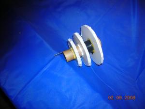
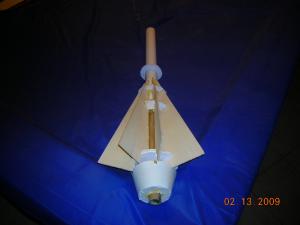
Booster Engine Mount
 |
 |
 |
- Take 3" piece of 24mm BT; then cut 1/8"x 3/8" slot in one end.
- Lay "flat" side of hook inline with slot and tape. *** I used a long piece of old wiper blade for hook and cut to length later.
- Cut out 3 "rear shroud centering rings. ***Tip: when I cut out middle of rings FIRST, I then took a spent engine and inserted and twisted to check for a tight fit. Then inserted engine in tube for support.
- Take largest rear ring and glue over rear engine mount WITHOUT covering slot in the mount. Be careful not to get glue on motor!!
- Glue middle and end centering rings and remove spent motor and let dry.
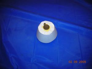
- While drying, cut out rear shroud. (You will see I include pattern, showing a "saw tooth design" on inside radius of shroud. Cut design in shroud. Much easier to glue.)
- Shape shroud, tape together on inside.
- Fold "teeth" over to inside and make a sharp crease. Straighten out.
- After center rings on engine tube have dried, take some glue and apply to edges of rings.
- Take shroud and slip over engine assembly. Be sure to get completely in.
- Spread some glue on smallest centering ring and fold shroud "teeth" down, holding till set. You may only be able to do a few @ a time. Let dry Thoroughly.
- Put a spent engine in "Main and rear " engine mounts.
- Slide together, lining up "slots" in engine tubes. The rear engine tube should slide over the Main engine about ½" and stay in place. ***Make sure rear Booster engine is as far forward as it will go WITHOUT disengaging the booster.
- Mark the rear engine hook , cut and bend to correct size.
- Cut shock cord mount and glue shock cord to it.
- Slide "loose" end of shock cord thru a BT55 coupler.
- Glue Shock cord mount to inside of BT55 containing engine mount far enough inside to be able to glue BT55 coupler. Glue Bt55 coupler and let dry.
- Cut other BT55 to length so when the two r put together , you have a rocket body 23" long, "without" rear shroud.
- Cut out Main Body centering rings. (u can take spare piece of BT55 to check fit).
- Take the "fin template" and mark 3", 3.5" ring where it will engage each fin. ****Note: you can mark 4" ring but, because of size, it won't line up with other two rings. You will have to do slots on this ring once it is mounted.
- Take care, cut a ¼" deep slot x 1/8" wide into each ring.
- Mark 1st slot on each ring with a #1 for reference.
- Make a fin from 1/8" "Basewood/plywood" as a guide to check fit of fins. It will also b used to as
guide for slots, and cut initial fin slots in 4" ring.
- ***You may want to fasten up rear shroud again w/spent motors to check placement of centering rings and fins.***
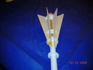
Fins and Body:
 |
 |
 |
 |
- Cut out 8 fins, and use sealer if desired.
- Use fine guide and cut slots in each fin: 1" from rear of fin, 1x1/4 deep. Next one 7" from end.
- Last slot is 2.5 " from previous slot and only 5/8" deep.
- These r initial slots. You may have to widen for proper fit.
- Slide center rings on BT one @ a time. ***If seems tight or binds, increase size of hole slightly. You can use a piece of BT55 to "shape" hole. (you want to maintain a fairly tight fit).
- Space rings approximately same distance as slots on fin.
- "Orientate" all 3 rings with #1's lined up.
- Take your "Guide Fin", ( the one made from plywood), and check slot lineup for first fin.
- You'll have to cut slots deeper in each ring, checking fit each time. You may not even need a slots for 4" ring, till ready to glue on fins, due to a "redesign", and lining up of fin with "center ring slots," I made for simplicity. (make recess higher, about 1 ¼").
- After you get a good fit for the fine on the center rings, take a "real" fin and glue in #1 slots of rings. (I kept breaking balsa fins, that why I recommended going to a sturdier material, such as basswood or Tims Tech report #29, gluing "notebook paper" to exterior of fin first for strength).
- Take guide fin and check next set of slot, adjusting for correct fit.
- Then glue 3 center rings in place.
- Glue all 8 fins in place, checking fit first with "guide fin".
- Cut out two "body templates". Make a slice at end of each one ¼-3/4" deep, 1" from end on each side. Fold over @ slices and straighten out.
- Depending upon which set of fins you start with, will determine what size template to use, medium or large.
- Lay template between fins, and gently push down. It should hang out rear, between fins 1", up to "slices."
- Check front of template and mark where template extends past fin.
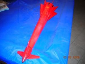
- Cut on the mark, down the ¼" fold mark on each side. Cut a "saw tooth" pattern in sides of body templates. Makes for easier gluing and smoothing out. ***see photo"***
- Before gluing fins, I made "fin supports," ½" x 1 ¼", and glue between ends of fins. Also, made a bevel on each end. **See photo**
- Glue in place and repeat for each set of fins. ***remember to check fit! (Center on BT) too. The rear of body template should be about ½-3/4" above body and rear shroud.
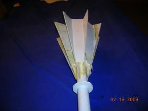
- Cut out "body templates," with "saw-tooth" design on edges and glue between fins.
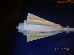
- Main Body Shroud: As I stated in beginning, not happy with the way this one turned out. You may want to shorten or find a different material or wrap around a "form" to keep smooth. Also, use same "saw-tooth" design for edges before gluing in shape of cone. Once glue, let DRY THOROUGHLY.
- I fitted over main body tube to fins. I marked where touched fins and cut slits about 1" long, in shroud. Keep fitting till you get a tight fit into slots, then glue and let dry thoroughly.
- Now comes a tricky part. Seams that r formed between "fins, body templates, main shroud have to be "filled." I opted to use "Elmers wood filler" and not happy with result. Friend recommended these tiny silicone beads you mix w/epoxy. Strong, light, and easy to sand after hardened.
- After seams dry, sand till smooth.
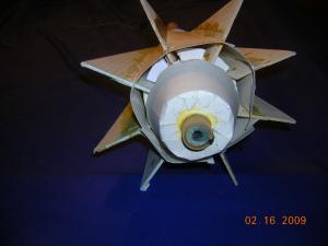
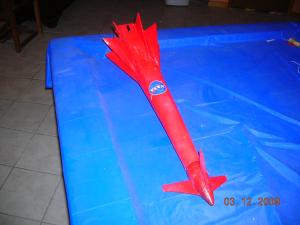
Nosecone Fins:
 Looking
@ picture of the rocket I was copying, "upper fins" aren't really in nosecone but, I liked this location
better. (You can opt to move out of nosecone, down body a few inches in "same configuration.)
Looking
@ picture of the rocket I was copying, "upper fins" aren't really in nosecone but, I liked this location
better. (You can opt to move out of nosecone, down body a few inches in "same configuration.) - Cut slits in nose cone ½" from end of "open" nosecone, about 2" long and 3/16-1/4" wide. ** b careful not to cut all the way thru to end of nosecone**. I mounted a piece of 1" aluminum angle iron to a piece of wood and clamped to my table as a guide.
- Fit fins in slots one @ a time, trimming slots till fins fit. Remove fins and put a ball of clay in tip of nosecone and press into place.
- Replace fins 1 @ a time til they "touch" in middle of nosecone and glue. (I opted for "gorilla glue" type). It foams up and becomes very strong). Let dry.
Nose Cone:
- Keep adding balls of clay, filling void in nosecone, and pressing into place. ****remember to allow room for end of nose cone to slide in.****
- Also, as you r filling void, assemble nosecone and check for CG with motors in main and booster BT's. (going to take a few ounces of clay to fill and balance rocket so CG approx. in middle.)
- Once clay pressed into place and you r satisfied w/location of CG, assemble nosecone.
Finishing:
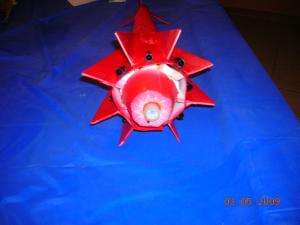
 Get 8 "regular" bic pen caps and cut off "pocket clip."
 - Paint rocket color of preference.
- After you r sure you have color of rocket and finished painting, sand a flat spot on each "pen cap," and glue in place between each fin above booster shroud. (These pen caps simulate 8 motors of rocket).
- Prep rocket and you r ready to fly.
- I would rate this build a 5++. Very difficult.
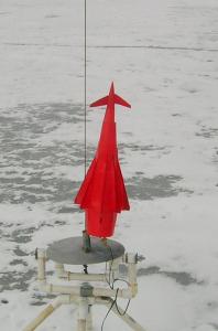
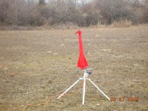
Flight:
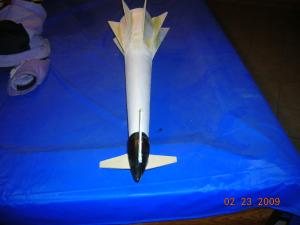
My first flight was very successful. I used a E9-4.
Preparation a little different than usual but, easy. After loading an 18" parachute, dusted with baby powder, and the wadding, I loaded the engine. I loaded it into the booster from the "inside." (The E9 is a much longer motor than the D.) Then I applied a little masking tape to the end for a "friction fit," and inserted it into main rocket body. It flew great! Relatively straight for the design, 11 fins, and the weight.
The shock cord, attached to rocket, was Kevlar. Then an elastic, tied to the Kevlar, which proved to b to weak. (will explain in next flight).
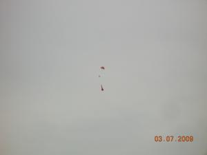
Parachute deployed perfectly and landed about 30 yards away.
SECOND FLIGHT
Another story. I designed this rocket to be an optional 2-stage. I prepped the parachute the same way. Then taped the booster, a D12-0, to the main motor, a D12-3, with scotch tape, and put a small slit in it, to help with separation. Once motors finished, I loaded it in booster stage first, from the "inside." Then added some masking tape to the main motor and "friction fit" it into main rocket. For whatever reason I couldn't get motors all the way in the main rocket body. ( I believe I used too much tape). At launch, it flew down range, weathercocked. Then deployed nosecone & parachute at a very low altitude of about 50 ft. The extreme weight of rocket snapped shock cord and rocket crashed. I'll be using a much heavier, and longer cord for the next flight. Still content with flight because it sustained minimal damage. This was my first 2-stage rocket of my own design.
THIRD FLIGHT
My third launch went absolutely perfect!! After adding a 1/4" "heavy" shock cord, I prepped rocket same way, with same motors. A D12-0 Booster, taped to a D12-3 Main. (Just make sure you have enough tape around main motor for "friction fit," and it's taped to booster. Motors ***all the way in*** main rocket. Slit cut in tape. Picture perfect flight!! Booster took it to a height of of about 75-100' and main an additional 100-200 ft. Perfect chute deployment and soft landing about 75' away.
Summary:
Pros: Challenge to design and build.Impressive liftoff w/2stages.
Cons: Very time consuming. Built a smaller version first to get aquainted with a "building technique" for adding 11 fins! Highly reccommend when tackling a new build when in experienced. Alighning body panels between fins a pain!
At almost 14 ozs., I would opt for a E30-4 motor for 1st flight. (E9-4) went well today. (use a spent motor in main body and tape E to it in booster stage, (friction fit spent motor). *****1/4" launch rod only!!****. 18" chute minimum!
Other:
Highly recommend "apogeerockets" tech report #29, "Take your rocket to supersonic speeds", for
durability of fins. Motor staging critical! Must b completely in main body so rear shroud close enough to it. Used two
1/4x 2" soda straws on a fin for launch lugs.
 |
 |