Scratch Klingon Special Forces Unit Transport Original Design / Scratch Built
Scratch - Klingon Special Forces Unit Transport {Scratch}
Contributed by John Thompson
| Manufacturer: | Scratch |
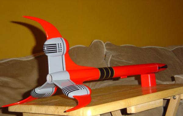
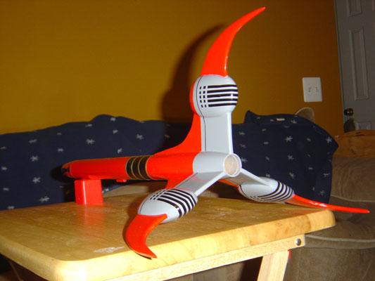
Klingon Special Forces Unit Transport
(Dedicate to Steve, a fellow employee, who passed away suddenly during the
build of this rocket)
Assembly Instructions
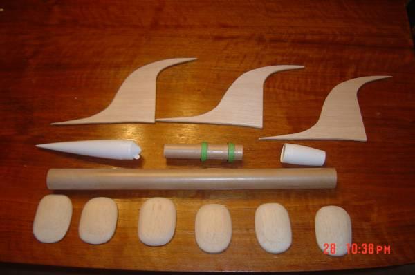
Parts List:
| Type |
Count |
Size |
Dimensions |
|
Nosecone |
1 |
NC 55 |
2 7/8 " long |
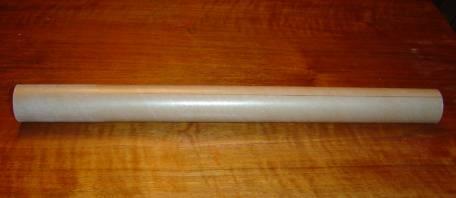
| Body Tube |
1 |
BT 55 |
15 ½ " long |
|
Tailcone |
1 |
TC 55 to 50 |
1 ¾ " long |
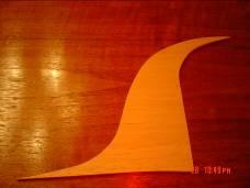
| Fins |
3 |
3/16 inch thick balsa |
6 ½ " root |
| Impulse/Warp Engine Pods |
6 halves |
Balsa |
2 ¼" x 3 ¼" |
| Engine Tube |
1 |
BT-50 |
4" long |
| Centering Rings |
2 |
CR-50 to 55 |
|
| Thrust Ring |
1 |
TR-50 |
|
| Engine Clip (optional) |
1 |
||
| Parachute Mounting Kit |
1 |
18 inch |
|
Engine Pod Template |
|||
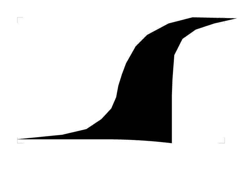
Fin Template |
|||
John Thompson's Word DOC Submission |
Word DOC |
Engine Mount Assembly
| **Note No engine clip is used. Friction fit and masking tape are used to keep the engine in place. This creates a cleaner look to the design. However, if an engine clip is desired, you can install the clip as you normally would. Make certain to cut out a small notch in one of the large green centering rings to accommodate clip movement. |
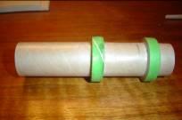
Using a 24mm engine mount found at most Hobby stores that sell rocketry items, find the light blue colored tube, a small green thrust ring, and two larger green Centering rings. On the engine tube, measure 3/8" from one end and make a mark. Find the tail cone and set aside.
Next, glue the small green thrust ring to the inside of the engine tube on the same end as the 3/8" mark. The end of the thrust ring should be flush with the end of the engine tube.
Smear some glue near the 3/8" mark all the way around the outside of the tube. Take one of the large centering rings and slide it up to the 3/8" mark through the glue line. Make a fillet around both sides of the centering ring.
Next, take the second large green centering ring and slide it onto the tube, but do not glue at this point. Take the tail cone and push it up against the second centering ring. Slide the tail cone and centering ring back until the end of the engine tube is inside the tail cone as far as it will go.
Make a mark where the centering ring stops, remove the centering ring and tail cone, and make a glue line around the tube slightly aft of the mark you just made. Take the second centering ring and slide it onto the engine tube, up to the mark, and through the glue line. Make a fillet on either side of the centering ring and set aside to dry.
 Once the glue on
the centering rings is dry, smear some glue approximately 2" on the inside
of the main body tube. Smear glue on the centering ring that is furthest away
from the thrust ring. Take the engine mount assembly and slide it into the main
body tube.
Once the glue on
the centering rings is dry, smear some glue approximately 2" on the inside
of the main body tube. Smear glue on the centering ring that is furthest away
from the thrust ring. Take the engine mount assembly and slide it into the main
body tube.
Before the second centering ring slides into the main body tube, slide the tail cone onto the engine mount and then use the tail cone to push the engine mount into the main body tube far enough so the tail cone will attaché correctly. Remove the tail cone and set main body tube aside to dry.
Once the glue has dried take some CA or Epoxy and glue the tail cone in place. Check engine fit. If engine will not slide into the Tailcone, "shave" off the end by sanding it with coarse sandpaper, or sand the inside of the Tailcone until the engine slides into the Tailcone/engine tube assembly correctly.
Fin Installation
On the main body tube, make three marks, 1200 apart for fin placement. Place the body tube on a door frame, and make a straight line down the body tube using each of the three marks as a starting point.
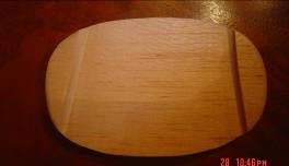
Take the fin pattern and place it on your choice of wood. Cut out three fins. Take some medium grit sand paper and sand all the curves until smooth. Sand root edge as necessary for a good fit along the tail cone. Do not glue to body at this point.
Take medium or fine grit sandpaper and round both the leading and trailing edges of all three fines.
Engine Pod Assembly
| **SPECIAL NOTE**: Remember that you need to have a right and left side pod half. Mark the bottom of three pod halves with the fin facing one direction, then mark the bottom of the other three pod halves with the fin facing the opposite direction. |
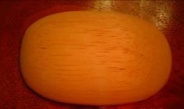
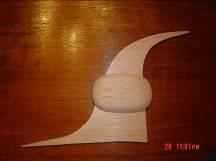
Take three pieces of scrap 3/16" balsa approximately 2 3/4" wide by 3 3/4" long. Glue and stack the balsa on each other. Using the supplied pattern as a guide, shape the pod to the pattern. Round the top portion of the pod to have an airfoil type shape; round at the front and tapers down in the back. Round all sides as well to give the pod a "bubble" look to it.
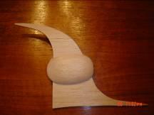
Once the top of the pod has been shaped (see below left), place the pod on one of the fins. Have the side of the pod 9/16" above the root edge of the fin. While holding the pod in place, turn the fin over and mark lines on the bottom of the pod where both edges of the fins meet the bottom of the pod.
Take a piece of heavy grit sand paper and a flat sanding "block", such as a paint stick, and sand a groove between the marks on the bottom of the pod. Sand a groove deep enough so the pod (see above right) will fit over the fin about half the thickness of the balsa.
Repeat the engine pod assembly instructions three more times, then turn the fin to face the opposite direction and mark the remaining three pods to create left and right pods.
Once all engine pod halves have been sanded and shaped, smear some glue inside the groove and glue the pod half onto the fin. Slide the pod down the fin as far as it will go. The bottom of the pod should be approximately 9/16" above the root edge of the fin. Repeat for the other side.
Repeat for the other three fins.
Once the engine pods are glued to the fins, glue the fin/engine pod assembly to the body tube using the fine line as a guide. The trailing edge of the fins should be flush with the aft end of the tail cone.
Shock Cord/Parachute Installation
Install shock cord and parachute according to your preferred method.
Launch Lug Installation
Glue launch lug onto body in your preferred locations.
Stability Test
Prep rocket as if you are going to launch it, using the largest 24mm engine you plan to use. Tie a length of string around the CG point. The CG should be approximately halfway between the fore root tip of the fin and where the fin starts to curve upwards.
Spin the rocket in a circle. If the rocket does not spin straight, place clay inside the nosecone until it spins straight.
Painting your Rocket
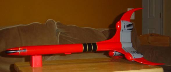
The base color for the taj is blood red, with grey, black, and gold detailing on the engine pods, fins, body, and nosecone. However, you may paint the rocket any color you wish.
Start by sealing all the balsa using your preferred method. Prime the entire rocket with an automotive grade primer that can be found at most automotive parts stores, Lowe’s, or Home Depot. The automotive grade primer fills imperfections very well, and sands fairly easy.
Once the rocket has been primed, "dust" a like coat of flat black paint over the entire rocket to give it a "splattered" look. The flat black will show all the imperfections, help you keep track of where you have sanded, where you need to sand, and will ensure the surface is flat for the next priming session. Allow the primer to fully dry.
Sand all the flat black paint off with medium-coarse grit sandpaper; such as 220 grit. Re-prime the rocket and "dust" the rocket with flat black paint. After the primer has dried, sand all the flat black off again, using fine grit sandpaper, such as 400 or 600 grit.
Once the flat black has been sanded off, the rocket is ready to paint. Clean the entire rocket with glass cleaner, such as Windex. The glass cleaner has Ammonia in it, which will not only remove the sanding dust, but it will also remove the oils left by your hands, which cause "fish eyes" in the paint.
Dry the rocket with paper towels and blow off any specks of dirt found on the rocket. Paint the rocket using the base color of your choice. Allow the color to dry thoroughly for several days.
If you wish to add more colors, mask off the areas not to be painted with tape and newspaper. Be certain to sand the area to be painted with fine grit sandpaper prior to applying the second color. If the area is not sanded, the color will peal off.
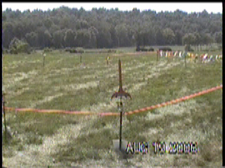
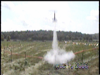
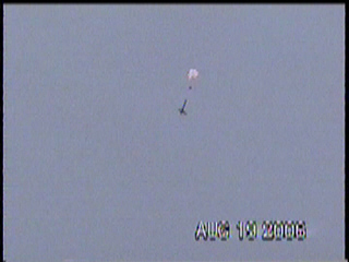
Flight
It was flown on a D12-7. The rocket was recovered safely with only 1 broken fin tip. (Here's the movie)
 |
 |