Scratch Little Joe 6 Original Design / Scratch Built
Scratch - Little Joe 6 {Scratch}
Contributed by Jeff Lane
| Manufacturer: | Scratch |
Brief:
Free paper scale model of 1959 Little Joe.
Construction:
Materials include 5 sheets of Canson Vellum Bristol 2 ply 8.5" x 11"
(14" x 17" cut in half to go through a letter size printer), one
8.5" x 11" sheet of 1/4" foamboard. 1 sheet of Grafix silver
metallic film (from grafixarts.com), Minwax Polycrylic Clear Gloss Protective
Finish (although a satin or matte finish would be closer to scale), white glue,
a 3' shock cord, some 1/8" dowel, a screw eye, some 5-minute epoxy, a
little red and white paint, a red marker, and some toothpicks. The Bristol and
silver film are available at artist supply stores.
I would rate this build a skill level 3. The parts can be downloaded here:
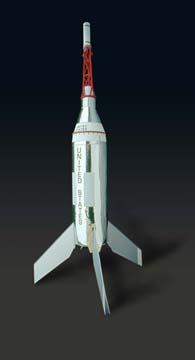
This is a free 1:31 scale model of the Little Joe. It's pre-Little Joe II, but they don't call it Little Joe One. In fact, this particular model is Little Joe 6, which was actually the second launch on October 4,1959, from Wallops Island. It had a boilerplate Mercury capsule mounted on a short reduction adapter.
After building one free paper rocket (M104-Patriot), a couple of limitations and/or peculiarities were revealed in paper models. One of the primary goals in creating a new model was to start with a design that has no compound nose cone curves. The Little Joe also has fins that are dimensional, which means they can be built out of paper and still retain rigidity. The original Little Joe fins are longer than the Little Joe II. It looked more stable and it turned out to be so much that no weight was needed in the nose.
The decision was made to use separate glue tabs made from scrap on all of the body tubes and shrouds rather than attached tabs because they look better. The only exception is the fins because integrated tabs work great there. Scrap paper in between the thickness of the Bristol and copy paper was used for the glue strips. The Bristol 2 ply paper is .015" thick. The silver material is .004" thick.
The wrap material is a silver-colored film from Grafix. It's manufactured with adhesive on one side and a mirror finish on the other side. In order to print on an inkjet printer, it must have an emulsion added which adheres to the metal but also allows the water based ink to dry on. To accomplish this, a water based acrylic polymer from Minwax was brushed on with a soft brush. A few small bubbles were carefully stroked out immediately while it was still wet. It has a milky look when wet but dries clear and glossy. After letting it dry for two hours, the sheet was printed up. The printer is a year old and because the rubber rollers had some "gotcha" gunk buildup, the slightly-still-tacky polyacrylic cleaned off the rollers. You may want to run a sheet of paper with polyacrylic or clear acetate with polyacrylic through your printer to clean off the rollers before doing the wrap. Of course, you put anything that's slightly tacky through your printer at your own risk. The imperfect printout was used for the prototype not only to save money but because the final product has that "used-and-abused" Star Wars look rather than a pristine new look. The inkjet print then dried overnight. Petroleum based clear coats like enamel and urethane won't work because the water in the ink has to be absorbed into the emulsion. The final product is pretty good. The gray printed areas in the attached PDF file were darkened because the prototype wrap turned out somewhat light, which is a problem primarily because of the high reflectivity of the material.
Gotchas: The metallic material starts to loosen and sag around the motor mount area after 3 launches. Adding some spray glue like Super 77 to the body tube before wrapping may eliminate or reduce this problem.
A slight gotcha is that while the ink on the metallic film doesn't smear and isn't tacky, it is extremely sensitive to re-wetting with moisture on the hands and is untouchable with any kind of moisture or water based cleaning solution.
Biggest gotcha: Do not force the corners of the seams together but allow them to fit according to their natural fold. If you try to force the corners to fit perfectly, you will wind up with some warping and hence induce spin during flight. In fact, it would be best to test build a couple of fins to get them right before doing the final fins. It's only paper.
If you're a paper purist, you could build this model without the metallic film or paint using just a red marker. A PDF of the body with simulated metallic shine is included for this purpose (little_joe_non-foil_option.pdf).
One option considered in the design process is a Strathmore Metallic gold paper #59802 for the body wraps that has an emulsion applied at the factory to allow inkjet printing. It doesn't have adhesive, so it would have to be glued on. It would look great and be easier but finishing in silver is closer to scale.
The body tube is printed and glued together with a glue strip, then the completed motor mount glued in. Test fit and sand the motor mount to accommodate the main body tube glue strip.
The metallic wrap is then added. It's slightly longer than the paper inner body tube to compensate for the material's thickness. On the prototype, the seam is within a hair's width with no overlap. There's an alignment line printed on the inner paper body tube to enhance wrap alignment.
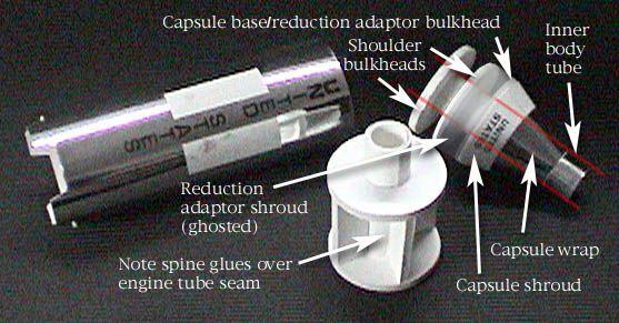
 Next is the Mercury capsule. It is composed of 2 identical
bulkheads around which the nose cone shoulder is glued and the larger diameter
of the reduction adapter abuts. A slightly smaller bulkhead is provided for the
capsule base/reduction adapter joint. Sand the bulkheads smooth and round.
Before beginning glue assembly, add the shoulder wrap to test fit into the main
body tube and sand the shoulder bulkheads if necessary to loosen fit and
accommodate the glue strip on the inside of the main body tube.
Next is the Mercury capsule. It is composed of 2 identical
bulkheads around which the nose cone shoulder is glued and the larger diameter
of the reduction adapter abuts. A slightly smaller bulkhead is provided for the
capsule base/reduction adapter joint. Sand the bulkheads smooth and round.
Before beginning glue assembly, add the shoulder wrap to test fit into the main
body tube and sand the shoulder bulkheads if necessary to loosen fit and
accommodate the glue strip on the inside of the main body tube.
The inner body tube of the Mercury capsule is built first using a glue tab. The capsule shroud follows using another glue tab. Slide the capsule shroud onto the inner tube from the front with glue around the inner tube at the contact joint that is printed on tube. The reduction adapter is assembled next by first making the reduction shroud with a glue tab and gluing it onto the slightly smaller forward bulkhead. Be sure to allow 1/32" of the bulkhead to protrude forward to seat the base of the capsule shroud. Then glue on the rearward bulkhead and allow most of the bulkhead to protrude to mount the nose cone shoulder. Slide the assembled reduction adapter onto the inner tube from the rear to test fit then glue around the inner tube. With a small amount of glue, seat it inside the capsule shroud base. The rearmost bulkhead is then added and the shoulder. The silver wraps must be added to the capsule last. The heat shield is simply a series of progressively smaller strips of Bristol carefully glued to the outside of the capsule/adapter joint.
Conceptually, the most complex aspect of this model is the bulkhead that the escape tower sits on. The inner nose cone body tube is made first using a glue tab and then the smallest diameter wrap starts around it. It's got 4 different widths and hence 4 progressively larger diameters of wrapped Bristol in the following order: 1) Fit outside the bottom end of the small nosecone inner body tube and inside the base of the lined shroud surrounding that tube. 2) Fit inside the lower body tube, which is the upper end of the completed capsule. 3) Extend out to provide the mounting platform for the escape tower. 4) Provide a smaller step to give a visual reduction for a scale look. Test fit each diameter into the respective tubes and shrouds and tear off the wrap when you've achieved a good fit.
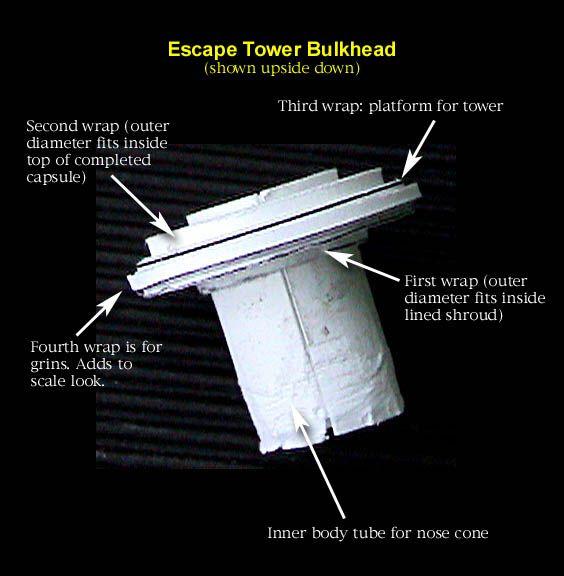
After the bulkhead is colored with marker, the lined shroud is made with a glue tab and glued on. The nose cone is formed with a glue tab and glued into place. The finished bulkhead and nosecone assembly can then be glued into the top of the capsule. The nosecone body tube circumference, which protrudes 1/32" from the front of the shroud so the nose cone can be glued, had to be sanded down for a good fit inside the nosecone on the prototype.
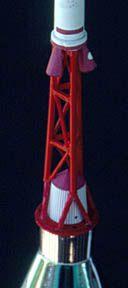
The escape tower scaffold was constructed using 1/8" dowel for the 3 main struts and toothpicks for the cross struts. The 3 main struts are 3.75" long including the split lower pieces. The prototype is very sturdy, has survived 4 flights, and looks good. It takes a couple of hours to make but the end product is worth it. However, if you're interested in trying a paper model for the first time using these plans but don't want to invest the time in the tower (or would like to put it off), you can certainly do so. It'll look and fly great without the tower.
The fins are easy to build, but here are four tips: 1) Before folding, score with a tool that is small enough to be accurate but doesn't cut. (A jeweler's screwdriver with a slightly rounded tip works great.) 2) Insert a small piece of flat aluminum or a small ruler to provide support inside the fins while gluing on the tabs. 3) Add a piece of 1/4" foamcore at the root edge and make sure it is recessed by 1/32" to allow for the curvature of the body tube for enhanced rigidity. 4) And do not force the corners of the seams together but allow them to fit according to their natural fold. If you try to force the corners to fit perfectly, you wind up with warp and hence spin. This is the biggest gotcha and in fact it would be best to test build a couple of fins to get them right before doing the final fins. It's only paper.
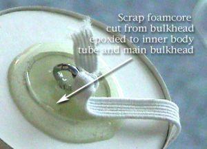 One of the pieces of scrap foamcore from the bulkheads is sanded
to account for the thickness of the inner body tube of the capsule and glued
inside 1/16" from the lower end of the inner capsule body tube. Epoxy a
screw eye into the center for one end of the 3ft shock cord and fasten the
other end with a folded paper mount.
One of the pieces of scrap foamcore from the bulkheads is sanded
to account for the thickness of the inner body tube of the capsule and glued
inside 1/16" from the lower end of the inner capsule body tube. Epoxy a
screw eye into the center for one end of the 3ft shock cord and fasten the
other end with a folded paper mount.
Finishing:
The only paint is a little flat white on the 4 panels on the main body and the
red on the escape tower scaffolding. The red on the heat shield and escape
tower bulkhead is done with a marker.
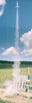
Flight:
Engine retention is done by friction fit. The RockSim simulation indicates that
a C11-3 will deploy a little early and a C11-5 a little late. I used a C11-5
(on 5/8/05) on the first two flights with ejection at 1 second past apogee
(~450 ft). They're beautiful, perfectly straight flights but with a significant
amount of spin. We're talking 10 cycles per second or so. No damage on either
flight. The first was with a 21" mylar parachute, which was too big, so I
went with an 18" chute for the second flight. I was able to catch the
landing then. A lot of wadding is required. The heat from the ejection charge
has begun to shrink the body wrap toward the top of the seam, so I'll add a
little liquid CA to try to reduce or eliminate that. Also, there's a
significant amount of ejection charge residue all over the body but that
actually makes it look more scale, so I'm not cleaning it. Third flight was on
a D12-5 (at C.R.A.S.H. on 5/21/05) with ejection just before apogee (~800 ft).
The parachute was a little sticky and stuck together, hence a quick descent
with one floppy fin, which was easily fixed. The fourth flight was with a C11-3
(at COSROCS on 5/28/05), and deployment was just before apogee but no chute
damage occurred. It was a beautiful flight. Recommended engines are B4-2, C6-3,
C11-3, C11-5, D12-5, E9-6.
Summary:
This is a great looking scale rocket that gets attention and flies high. An E9
would be spectacular if you could get the fins straight (simulations calculate
~1200 ft). The shrinking and sagging of the metallic wrap is a problem. If you
have some or most of the materials, it's free. Even if you have to purchase
some of the materials, it's fun and cheap.
 |
 |