Scratch Lucky 13 Original Design / Scratch Built
Scratch - Lucky 13 {Scratch}
Contributed by Layne Pemberton
| Manufacturer: | Scratch |
Brief:
Over the last few months I have built several paper rockets, including a V2,
Friede, and N-1 downloaded from Ralph
Currell's website. I thoroughly enjoyed the experience, too, so the next
most feasible step was to build and fly a paper rocket. Thus was born Lucky
#13. You will find out about the name later. It is patterned after the SDI
mid-course intercept missile as represented in Scientific American
magazine much in the same way reality TV shows are patterned after real life.
It is constructed entirely of poster board, foam core, and cardstock. To make
the challenge a little more interesting, I decided to build Lucky #13 solely
from parts and materials on hand. She has a 29mm motor mount, an ejection
baffle, positive motor retention, poster board fins and body tube, cardstock
nosecone, foam core centering rings, styrene and balsa details, and lots
of nose ballast. A 24" chute is slated for recovery purposes.
Construction:
Here is the parts list:
- 1 package of cardstock paper
- 1 or 2 sheets of poster board
- ~2.2oz of nose cone ballast
- 75" of 9/16" tubular nylon
- 1 Public Missiles, Ltd. PAR-24R 24" nylon parachute
- 1 2.5" x 1/16" birch plywood bulkhead
- 2 screw eyes with two washers and one nut each
- 1 0.065" styrene sheet
- 1 0.185" balsa sheet
- 1 wire clothes hanger for motor retainer
- 1 3.0" x 1.5" x 0.25" aircraft plywood centering ring
- 1 2" x 0.25" aircraft plywood bulkhead
- Tiny wood scraps
- 2 3/8" brass launch lugs, 2" long
- 1 24" x 24" sheet of foamboard
- Several cans of Krylon paint and primer
- Elmer's polyurethane glue
- thin and medium viscosity CA
- A X-Acto knife with several new blades
"A beginning is the time for taking the most delicate
care that the balances are correct."
--from Dune by Frank Herbert
From the beginning this project was the author's introduction to the three B's of Rocketry (or anything else for that matter): Botching, Butchering and Buggering. Something major went wrong at almost every step of construction and it was usually as a result of being careless or hurried but there were times when Lady Luck, Fate, and the Fairy Godmother abandoned the project. Thus, this paper rocket was dubbed Lucky #13.
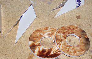
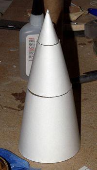
From the equation for the circumference of a circle, C=πd, the length of poster board needed for a 3.03" body tube was calculated and the poster board was cut accordingly to a length of 17.95" to included both upper and lower body tubes. Once cut the tube was rolled through a succession of smaller diameters starting with a four inch tube and finally ending up rolled inside a segment of 3" PML Quantum Tubing. This was left in place while the nose cone shrouds were fabricated. VCP was used to print shroud templates for the nosecone and a fin position wrapper onto cardstock. The shrouds were cut and glued together using the same method as Ralph Currell uses in his paper rocket plans, utilizing crenulated strips and minimal amounts of CA. After the third set of shrouds, a lovely nosecone without a single wrinkle or CA fingerprint was finally fabricated.
 The fin and
centering ring templates were printed from the RockSim file. The two centering
rings were traced onto the foamboard and carefully cut out while the fin
template was set aside. To be on the safe side, centering rings are cut just a
tad large and trimmed to a perfect fit. This was about the only part of the
project not affected by the Three B's. Fabricating a motor mount tube from
poster board was assumed to be a straightforward affair of rolling a motor in
the poster board and cutting it to size. However, the tube produced after
rolling two layers of poster board around a 29mm RMS casing was, shall we say,
botched. The edges would not meet up square, the tube was deeply creased from
stem to stern and later it was discovered that a 29mm casing would no longer
fit inside the tube. This could be due to the use of polyurethane glue and it's
foaming properties in construction of the motor mount tube. While still rolled
around the motor casing, urethane glue was smeared beneath the long edge of the
tube and the edge taped into place. Once
The fin and
centering ring templates were printed from the RockSim file. The two centering
rings were traced onto the foamboard and carefully cut out while the fin
template was set aside. To be on the safe side, centering rings are cut just a
tad large and trimmed to a perfect fit. This was about the only part of the
project not affected by the Three B's. Fabricating a motor mount tube from
poster board was assumed to be a straightforward affair of rolling a motor in
the poster board and cutting it to size. However, the tube produced after
rolling two layers of poster board around a 29mm RMS casing was, shall we say,
botched. The edges would not meet up square, the tube was deeply creased from
stem to stern and later it was discovered that a 29mm casing would no longer
fit inside the tube. This could be due to the use of polyurethane glue and it's
foaming properties in construction of the motor mount tube. While still rolled
around the motor casing, urethane glue was smeared beneath the long edge of the
tube and the edge taped into place. Once
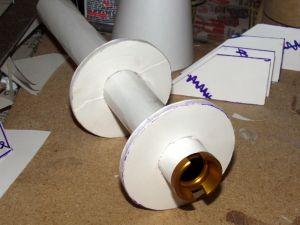 cured, the
motor was removed and the centering rings slid onto the motor mount tube, one
1/2" from the aft of the tube, the other 5.5" from the aft of the
tube. Both rings were attached with urethane glue. Later it was discovered that
once mounted in the body tube, the aft most centering ring was too close to the
end of the motor tube and hindered motor removal. Without sufficient poster
board to create a new one, the motor tube was buggered but still usable. Be
advised: place the aft centering ring a distance greater than 1/2" from
the aft of the motor tube.
cured, the
motor was removed and the centering rings slid onto the motor mount tube, one
1/2" from the aft of the tube, the other 5.5" from the aft of the
tube. Both rings were attached with urethane glue. Later it was discovered that
once mounted in the body tube, the aft most centering ring was too close to the
end of the motor tube and hindered motor removal. Without sufficient poster
board to create a new one, the motor tube was buggered but still usable. Be
advised: place the aft centering ring a distance greater than 1/2" from
the aft of the motor tube.
The fins were traced in what appeared to be a butterfly-like pattern onto the posterboard with the single fin stencil being traced twice for each fin with the two traces connecting along the tip cord. They were then cut out, folded along the tip cord, and the leading edge was secured with CA leaving the rear edges open. The appearance of thickness in the fins was a pleasant surprise and added to the overall effect.
On to the body tube, the now pre-rolled tube was marked 3" from one end and cut perpendicular to the long edge to produce the upper body tube. Strips of poster board were cut to the length of each body tube and about one inch wide to be used to close the body tubes. CA was spread along the inside of the long edge of the tubes and the closure strips set in place with a 0.05" overhang. The edges of the closure strips were then smeared with CA and the edges of the tubes pressed together. The normal method of tube creation is to apply pressure along the inside of the seam onto a flat surface to ensure a smooth seam. While butchering the tube closure job though, it was discovered that a PML 3" coupler was the perfect size to roll the body tube into its final state. Thus, the body tubes were rolled around the couplers, the closure straps coated with CA, the edges pressed together against the internal coupler, and they were taped into place until dry. Only at this final stage was it noticed that the body tube had not been cut straight or square and the edges would not meet up. Can anyone say botched? The result was a pretty decent seam, just try and not notice all the gaps, CA fingerprints, and smudges. To connect the upper and lower body tubes, a coupler was fabricated by rolling a 3.75" section of poster board inside the lower BT and running CA down the inside seam. Once again the Fates were absent and the coupler ended up being undersized. Butchered? Strips of tape were used to fill the gaps and assure a snug fit. I smeared adhesive around inside the aft portion of the upper body tube and inserted the coupler halfway inside.
 While
preparing to insert the completed motor tube into the body tube, I noticed that
no provision had been made for positive motor retention. I hurriedly bent a 10
inch section of hanger wire into a flattened "U" shape ~3/4"
across the base of the "U" and two holes were drilled in the seam
between the motor tube and aft centering ring to accommodate the legs of the
wire. The results of me rushing was the holes were buggered and the motor
retainer would just barely catch the rim of a 29mm casing once it was inserted.
A bit of cursing and grinding later the motor retainer was functional and tied
into place with twine, which had been smeared with polyurethane glue. Once this
hideous monstrosity was dry, a generous portion of polyurethane glue was spread
inside the body tube 1.25" and 6" from the aft end of the body tube.
The motor mount assembly was slid into place until the aft most centering ring
was recessed 1.25" from the base of the body tube. I stood the body tube
upright and supported the aft centering ring with a piece of scrap until the
glue was dry. I then applied fillets on both centering rings.
While
preparing to insert the completed motor tube into the body tube, I noticed that
no provision had been made for positive motor retention. I hurriedly bent a 10
inch section of hanger wire into a flattened "U" shape ~3/4"
across the base of the "U" and two holes were drilled in the seam
between the motor tube and aft centering ring to accommodate the legs of the
wire. The results of me rushing was the holes were buggered and the motor
retainer would just barely catch the rim of a 29mm casing once it was inserted.
A bit of cursing and grinding later the motor retainer was functional and tied
into place with twine, which had been smeared with polyurethane glue. Once this
hideous monstrosity was dry, a generous portion of polyurethane glue was spread
inside the body tube 1.25" and 6" from the aft end of the body tube.
The motor mount assembly was slid into place until the aft most centering ring
was recessed 1.25" from the base of the body tube. I stood the body tube
upright and supported the aft centering ring with a piece of scrap until the
glue was dry. I then applied fillets on both centering rings.
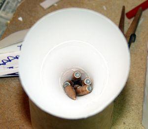
 RockSim
indicates the need for ~2.2 oz of ballast in the nose to attain stability
across the range of engines I planned on using. Once again staying with the
"Thou shalt not purchase" philosophy, the house was searched for
something to use as nose weight. The result being a handful of 163 grain .30
caliber FMJ bullets purchased in bulk years ago for my reloading habit. Fishing
sinkers would have been much less expensive but I don't fish. According to my
ancient triple beam scale, seven of the bullets weighed in at 2.34 ounces,
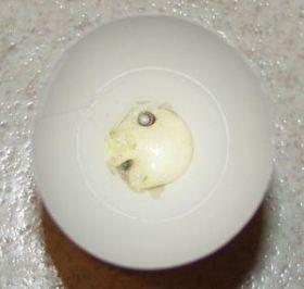
which would do nicely. The ballast was secured in the tip of the nosecone with
a generous portion of polyurethane glue and set aside to cure. While dry
fitting the bulkhead into the nose section, the weight in the tip flipped the
nosecone out of my hand where upon it landed on the floor crushing a section of
the lower shroud. So much for my perfect nosecone. Once the ballast has been
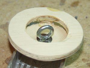
effectively sealed in the tip of the nosecone, the 2.5" bulkhead and
eyelet, also found in the scrap pile, were assembled and glued inside the nose
cone with polyurethane glue. Set aside and support upright till dry. After the
glue has set, I want you to be forewarned as polyurethane glue cures slowly and
remains tacky even after reaching the foaming stage. A short length of shock
cord material ~18" was threaded through the eyelet for attachment of the
recovery system. The completed nose section was then glued to the upper stage
BT utilizing a crenulated strip and minimal amounts of CA as described in the
nosecone assembly section above.
RockSim
indicates the need for ~2.2 oz of ballast in the nose to attain stability
across the range of engines I planned on using. Once again staying with the
"Thou shalt not purchase" philosophy, the house was searched for
something to use as nose weight. The result being a handful of 163 grain .30
caliber FMJ bullets purchased in bulk years ago for my reloading habit. Fishing
sinkers would have been much less expensive but I don't fish. According to my
ancient triple beam scale, seven of the bullets weighed in at 2.34 ounces,
which would do nicely. The ballast was secured in the tip of the nosecone with
a generous portion of polyurethane glue and set aside to cure. While dry
fitting the bulkhead into the nose section, the weight in the tip flipped the
nosecone out of my hand where upon it landed on the floor crushing a section of
the lower shroud. So much for my perfect nosecone. Once the ballast has been
effectively sealed in the tip of the nosecone, the 2.5" bulkhead and
eyelet, also found in the scrap pile, were assembled and glued inside the nose
cone with polyurethane glue. Set aside and support upright till dry. After the
glue has set, I want you to be forewarned as polyurethane glue cures slowly and
remains tacky even after reaching the foaming stage. A short length of shock
cord material ~18" was threaded through the eyelet for attachment of the
recovery system. The completed nose section was then glued to the upper stage
BT utilizing a crenulated strip and minimal amounts of CA as described in the
nosecone assembly section above.
From the beginning, the intention was to use an ejection baffle just because it was something different and the baffle system on the Aerotech Strongarm works quite well. Rifling through the scrap pile turned up a botched 3-1.5" centering ring (to be the baffle ring), a 2.1" bulkhead (used as the deflector plate) and a 2.1" wood ring of questionable origin. All three these parts were from 1/4" aircraft plywood. Three 1/4" sections of the mystery ring were cut to use as stand-offs between the baffle ring and deflector plate and glued equidistant around the circumference of the center hole in the baffle ring. The deflector plate was then glued atop the stand-offs and the assembly set aside to cure. After curing, it was time to add an eyelet for the shock cord mount but a question sprang forth in my mind. "Why should the eyelet be mounted facing out from the deflector plate as in the Strongarm so that the plate would be A) pushed away from the spacers on the baffle ring during ejection and B) pulled away from the spacers under the forces of recovery deployment? This seemed to focus the combined forces of ejection and deployment on the weakest portion of the baffle: the glue joint. In another sweaty flash of mad inspiration, the baffle was flipped over with the eyelet mounted facing up through the hole in the baffle ring. This configuration would in effect pull the deflector plate into the spacers and baffle ring under load and distribute the forces more widely.
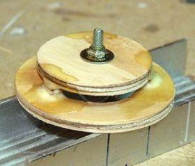
I dabbed a bit of glue on the threads of the eyelet to hold it in place, as the nut was inaccessible once the baffle was mounted. A ring of adhesive was smeared inside the lower body tube ~3" from the fore end. The baffle system with the eyelet up was slid into place and set aside to cure. It wasn't until this time that the baffle ring was realized to be undersized and slid, slipped, and flipped freely inside the lower body tube. A couple of wraps of tape around the circumference of the ring cured the problem but by then the entire inside of the lower body tube, baffle assembly, floor, author, and entire desk top were covered in adhesive. (Pick a "B".)
After scrubbing the adhesive from wherever it could be found, the baffle system had cured in place, so a snap ring was tied to the shock cord and intended to snap onto the baffle eyelet. To my dismay though, the baffle system was seated so far back as to hinder hooking onto the eyelet. With a bit of wiggling and tongue holding, it was possible to hook and unhook from the eyelet, but it is no church picnic. Another warning: seat the baffle system just deep enough to allow parachute storage but not too deep to reach the eyelet.
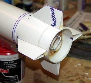
 Then it was
time to move on to the fins. After marking the lower body tube with the body
wrapper guide, the fins were aligned and tacked into place with medium CA. I
then applied thin CA to the body/fin joints to adhere along the entire contact
surface. During the gluing process one fin slid forward a bit and out of
alignment with the other fins but was not noticed until the adhesive had set.
Butchered another one. To afford more support, the inside of the fin/body seams
were coated with polyurethane glue.
Then it was
time to move on to the fins. After marking the lower body tube with the body
wrapper guide, the fins were aligned and tacked into place with medium CA. I
then applied thin CA to the body/fin joints to adhere along the entire contact
surface. During the gluing process one fin slid forward a bit and out of
alignment with the other fins but was not noticed until the adhesive had set.
Butchered another one. To afford more support, the inside of the fin/body seams
were coated with polyurethane glue.
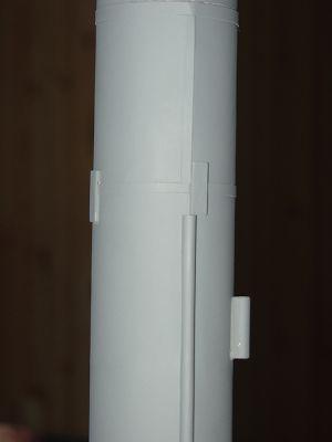
A number of cosmetic details from images of the real missile were added to this model including a 3/4 length conduit made of half a straw, three circumferential styrene rings to simulate stages, and four "blocks" around the upper styrene ring assumed to be guides to keep the actual missile aligned in the silo during launch. The straw conduit and a final strip of styrene were attached with thin CA along the seams of the body tubes to hide the raw edges.
Finishing:
All dents, dings, gaps around the joints and any other unsightly blemishes were
filled with DAP Fast 'N Final Lightweight Spackle and sanded smooth. At this
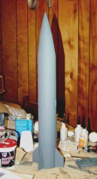
time Lucky #13 wears only a couple of coats of gray primer.
Flight:
RockSim puts the CG at 13.74” the CP at 17.19”and the mass at ~17.9
oz when loaded with an F40-7.
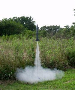
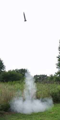
Being unsure of the performance of this design the first flight was attempted with the rocket “in the white” as not waste a good paint job on a crack-up. A 24mm E18-4 RMS was assembled but my luck with Copperhead igniters reared its ugly head and not a single igniter would ignite let alone start the motor. But this may have been a blessing in disguise as the past performance of the 24mm casing consisted of two CATO's and no successful launches.
See the flight logs below.
Summary:
I actually look forward to the day when I can do a rebuild of Lucky #13 and get
it right. Never in my wildest nightmares did I ever imagine that working with
paper would be such a hassle, yet several hard lessons were learned. RockSim
indicates the design is solid and should fly nicely on a wide range of motors
and now that she wears a coat or two of primer, she doesn't look that bad.
Updates will follow.
Other Reviews
- Scratch Lucky 13 By Tommy Owens (August 1, 2009)
( Contributed - by Tommy Owens - 08/01/09) Brief: When putting together my box of parts I had no idea what to expect and so crammed as much of my rocket "junk" into the box as possible. After starting the contest, however, I realized that I did not have the experience or engine power to cram everything onto one rocket. Because I had no idea what to build I did what ...
 |
 |