| Manufacturer: | Scratch |
 Brief:
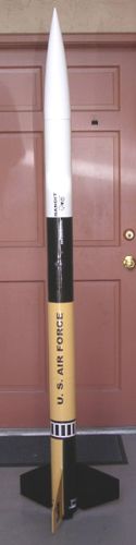
The MegaBandit is a scratch built 3X upscale of the Estes Bandit and designed as my first K powered rocket. It's a 4" diameter, 79.5" long fiberglassed rocket with a 54mm motor mount. It was designed for dual deployment with altimeter.
Construction:
Components consisted of Giant Leap 3.9" phenolic body tubes cut to 21", 22" 1.5", and 17" long pieces. These were custom cut by Giant Leap and the 22" body tube was custom slotted for three fins to my dimensions. The 17" airframe was for the drogue section while the 21" airframe section was used for the main. The 1.5" ring was used for mounting the power switch to the electronics bay. 4 Phenolic tube couplers, a 18" 54mm phenolic motor mount, and three 3/16" plywood coupler bulkplates and tube bulkplates were also from Giant Leap. Fins were cut from 3/16" aircraft plywood and were direct upscales of the original Bandit fins with tab extensions added for through-the-wall fin attachment and airfoiled at the leading edge. Three motor mount centering rings were made from 1/4" plywood. A PML 3.9" nosecone finished it. I used the Aero Pack retainer for motor retention.
I used 30 minute hobby epoxy for tack gluing and West Systems epoxy throughout the rest of the build including fiberglassing. Construction was similar to all high power rockets. The motor mount comprised an 18" long 54mm diameter phenolic motor tube with three centering rings designed so the fins were sandwiched between the bottom and middle ring. The top centering ring was fitted with two sections of 1/4" all-thread, nuts, and washers to allow connection to a zipperless tube coupler. The middle and top centering rings were attached to the motor tube and mount installed. The fins were then tacked in place. All internal and external fin joints were reinforced with West Systems epoxy mixed with milled fiberglass and the same mixture was poured on top of the centering rings to reinforce the paper-ring joint. The bottom centering ring was then epoxied in place.
Construction of a zipperless coupler started by making a stuffer coupler. This involved removing a lengthwise slice from one tube coupler so that it fit inside another coupler. A coupler bulkhead and tube bulkhead were epoxied to one end of a tube coupler and the stuffer coupler slid and epoxied inside the open end of this coupler until it met flush with the bulkheads. The excess of the stuffer coupler was then trimmed flush with the outside coupler. A 1/4" U-bolt was attached to the bulkheads and holes were drilled to align with the all-thread extending from the top centering ring of the motor mount. The completed zipperless coupler was slid onto the fin can, passing the all-thread through the holes and by wing nuts and washers.
The completed fin can and two other airframe tubes were fiberglassed with 6oz cloth followed by a 1.5oz veil layer. Once completely cured, the tubes were fine sanded to remove rough and high spots and blend seams. Superfil epoxy-based filler was used to even everything out and then it was sanded smooth.
An avionics bay was constructed using the coupler-in-coupler method used in making the zipperless coupler with the stuffer coupler also shortened to allow proper seating of coupler bulkheads at both ends. A coupler bulkhead and tube bulkhead were epoxied to the drogue end of the bay and the stuffer tube epoxied in place as with the zipperless coupler. A 1/4" eyebolt and two 8.5" x 1/4" sections of all-thread with nuts and washers were installed into the drogue bulkheads. The 1.5" section of fiberglassed body tube was centered along the coupler. A 1/2" mounting hole for the arming switch from Missile Works and four 9/64" vent holes evenly spaced were drilled in the section of body tube through the coupler. A coupler bulkhead and tube bulkhead were epoxied together, holes drilled to align with the all-thread and a 1/4" eyebolt epoxied in place. This bulkhead assembly can then be connected to the avionics bay using wing nuts after the altimeter is inserted and proper igniter and electrical connections made. A sled was made from plywood and paper launch lugs to mount the altimeter. This can then slide inside the avionics bay along the all-thread rods and be interchangeable between rockets. A 1/2" PVC end cap and terminal posts were epoxied to the bulkplates at both ends to hold ejection charges and allow easy connection of e-matches.
A 54mm Aero Pack retainer was epoxied to the motor tube with JB Weld.
Three rail buttons were then installed, 2 in the fin can and one in the drogue airframe. Vent holes were drilled in the main and drogue parachute bays. The electronics bay was secured to each of the parachute bays with three #6-32 truss head screws using T-nuts epoxied to the inside of the electronics bay. The other airframe sections and nose cone were connected using styrene rod to prevent drag separation but allow easy separation upon ejection charge ignition.
Finishing:
Preparation for finishing was 2 coats of gray sandable primer, sanded with 400 sandpaper between coats. Color coats were 2 coats of each color. Color scheme was identical to the original Astron Bandit using Rustoleum paints for the white and black. The Krylon yellow was too bright for my tastes so I chose a Home Depot brand in Butterscotch. Decals were 3X upscale printed on self-adhesive vinyl from Tango Papa.
Flight:
I'd been waiting almost two months to get MegaBandit into the air. On November 11, 2005, I arrived at the launch site to be slightly disappointed with clouds (although not low enough to void the flight attempt) and fairly strong winds. I debated for some time before deciding to go ahead with the launch. It took a long time to prep the rocket for flight since this was my first altimeter flight. Once the recovery system and altimeter were installed and secured, I loaded in the AMW K530GG motor and headed to the pad. MegaBandit was loaded onto the rail, the igniter installed and the altimeter armed. The LCO announced the flight. After waiting briefly for the winds to die down a bit, countdown commenced and the was button pushed. The AMW motor soon roared to life sending MegaBandit strongly off the pad and streaking skyward under a beautiful green flame. The strong winds caused a lot more weathercock than I had hoped but still it was beautiful!
Recovery:
Dual Deploy recovery was controlled by an Adept ALTS25 altimeter. MegaBandit was set for drogueless recovery at apogee using 30ft of 1/4" tubular Kevlar for harness. Main chute was a 52" SkyAngle connected to 20ft of 1/4" tubular Kevlar recovery harness and set to deploy at 600ft. Clouds obscured the exact moment of apogee deployment visually, but the pop of the drogue ejection charge was heard. The rocket then proceeded it's free fall descent out of visual contact. It was picked up free falling as intended several seconds later. Tension filled moments passed as the rocket fell and I awaited deployment of the main chute at 600ft. It came right on cue. The chute inflated and MegaBandit drifted its final few hundred feet down for a safe recovery. Success!!! My first altimeter/dual deployment-based flight could not have been more perfect. I walked to retrieve the rocket and found it to be in perfect condition sprawled out on the soft grass.
Summary:
This project was filled with firsts for me. It was my first totally scratchbuilt HPR, my first fiberglassed rocket, and my first rocket using dual deployment with the required electronics and construction of an altimeter bay. It was also my first experience with AMW motors. The objective was to gain experience with advanced construction techniques and get familiar with flying electronics. These goals were achieved with great success culminating in my most gratifying flight to date, even more than either of my certification flights. And, in the process, I set a new personal altitude record. My next goal is the 1 mile flight.
 |
 |