Scratch Mercury Transport 18mm Original Design / Scratch Built
Scratch - Mercury Transport 18mm {Scratch}
Contributed by Nick Esselman
| Manufacturer: | Scratch |
 The Mercury Transport is a new design from
Essence Aerospace Technologies (EAT). Its main purpose is to transport 4
passengers the 91.8 Million Kilometers to the planet Mercury for observation,
study and experimentation in a high temperature, zero gravity, high
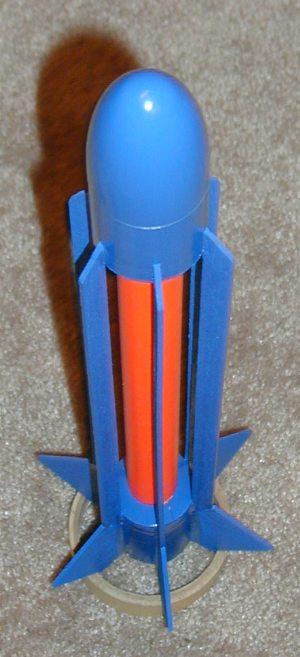
sun-radiation environment. The Mercury Transport has fins that are suspended
over the inner Fusion Proton Rod Reactor Core. The fins are in a test
configuration for future interstellar travel and to assist in cooling the core
as the ship passes close to stars (such as our Sun). The ship is primarily
designed for long distance travel. In fact, 95% of the entire ship is a reactor
to allow the ship to travel the distance needed.
The Mercury Transport is a new design from
Essence Aerospace Technologies (EAT). Its main purpose is to transport 4
passengers the 91.8 Million Kilometers to the planet Mercury for observation,
study and experimentation in a high temperature, zero gravity, high
sun-radiation environment. The Mercury Transport has fins that are suspended
over the inner Fusion Proton Rod Reactor Core. The fins are in a test
configuration for future interstellar travel and to assist in cooling the core
as the ship passes close to stars (such as our Sun). The ship is primarily
designed for long distance travel. In fact, 95% of the entire ship is a reactor
to allow the ship to travel the distance needed.
I began preparing to build a Mid-High Power rocket with this unique (at least I've never seen anything like it) fin and body configuration. So, in preparation I wanted to build a smaller 18mm prototype to test design and stability. This article describes the assembly and performance of the prototype which turned out to be a nice rocket in itself. There is also a thread on The Rocketry Forum that I initiated when I started this process.
I decided to start with an Estes Big Bertha kit to get the larger diameter tube, motor mount, parachute and especially the nose cone. So with that being said, here's my parts list:
- (1) 2" length BT60 (1.637" diameter) Tube - From Big Bertha Kit
- (1) 3" length BT60 (1.637" diameter) Tube - From Big Bertha Kit
- (1) PNC-60MS Nose Cone - From Big Bertha Kit
- (1) 18mm Motor Tube - From Big Bertha Kit
- (1) 18mm Thrust Ring - From Big Bertha Kit
- (1) 18mm Motor Hook - From Big Bertha Kit
- (2) 18mm to BT60 Centering Rings - From Big Bertha Kit
- (1) 18mm to 24mm Centering Ring - Use a cut from a spent 24mm motor if needed
- (3) 24mm to BT60 Centering Rings - Cut from 1/16" balsa or shoebox
- (2) 24mm to BT60 Transition - Cut from the Big Bertha Kit's Picture Card
- (1) 3/32" Thick, 3" x 36" Balsa
- (1) 15" length of 24mm Apogee Tube
- (1) 32" of Kevlar® Shock Tether
- (1) 24" Elastic Shock Cord - From Big Bertha Kit
- (1) 1/8" Launch Lug / Cut in Half - From Big Bertha Kit
- (1) 18" Parachute with Center "Estes" Circle cut out - From Big Bertha Kit
CG=11 1/2" from top (see RockSim File)
ASSEMBLY:
- Cut a 2" and a 3" section off of the BT60 tube. I use a piece of paper to wrap around the tube to ensure it is even then draw a line all the way around. Alternatively, I use masking tape to make an even circle around the tube. Use a sharp hobby knife to make the cuts. Usually two or three passes. Don't try to do it on the first shot and take your time. Cut 2" off one side of the BT60 and 3" off the other so that you have perfect, factory cut edges on each side.
- Cut the Apogee 24mm tube to a length of 14.5".
- Cut out (3) Centering Rings from 1/16" balsa. I used the centering rings provided with the Big Bertha kit to cut the outer edge and then traced the 24mm tube for the inner circle. I then used sandpaper to shape them to fit. Test fit them over the 24mm tube and into the BT60 tubing.
- Assemble the motor mount per the Big Bertha Instructions with (1) major exception. Leave the upper centering ring 3/4" from the top of the tube.
- Tie the Kevlar® Shock Tether around the motor tube top (that 3/4" space) and then slide the 18mm - 24mm centering ring over the Shock Tether and glue even to the top of the Motor Tube. Wait until dry. Thread the Shock Tether through the Motor Tube to get it out of the way.
- Glue the motor mount into the 3" section of BT60 tubing so that the lower centering ring is flush with the bottom and your cut edge is up. Let dry.
- Slide one of centering rings you made over the 24mm tube and test fit it into the lower (3") section. The tube should slide over the 18-24mm centering ring on the motor tube and down until it rests on the motor mounts upper centering ring. The push the balsa centering ring down until it fits just inside of the 3" section. Mark the 24mm tube for the alignment of this centering ring. Pull it all out and slide the centering ring to 1" or so higher than the mark you just made. Apply glue to the inside of the 24mm tube and around the mark on the 24mm tube. Slide it back into the 3" section onto the inside centering ring until it touches the motor tube centering ring. Slide down the balsa centering ring until it is just inside and flush with the 3" section. Let dry.
- Place a mark at 1/2" on the top of the 24mm tube. Slide another balsa centering ring onto the 24mm tube about 1" of so beyond the 1/2" mark. Apply a ring of glue at the 1/2" mark and at the very end of the tube. Slide the balsa centering ring up to the 1/2" mark. Place the 3rd balsa centering ring onto the top of the 24mm tube so that it is flush. Make sure both centering rings are equally spaced all the way around. Let dry.
- Put a ring of glue on the inside of the 2" section of BT60 tubing on the cut edge side. Slide the 24mm tube into the BT60 tube until the lower centering ring is flush with the bottom. Lay this assembly on a table and roll it gently to ensure the bottom 3" tube and top 2" tube are in alignment. Use a straight-edge to check.
- (10) Cut the transitions using the calculations in Tim Van Milligan's Model Rocket Design and Construction Book. I used the formulas, but cut full circles and then sized the transition from the over-lap. Tim's book does show you how to calculate the angle/degrees that could be measured, but I found my method to work fine.
- Glue transitions in place. If they are slightly bigger than the BT60 tube, that's okay. It can be trimmed with a sharp hobby knife after the glue has dried.
- Cut the (6) Cooling Fins from the 3/32" Balsa. They are 11mm wide and 14 5/8" long. The angle is cut on both ends by measuring 1/2" on the top side and cutting from that point to the lower corner. Unfortunately the grain running parallel with the length of the Cooling fins is the easiest cut and realistically the only way of having this 1 piece. The makes the attachment a little vulnerable to breaking along the grain.
- Cut the (6) Main Fins from the 3/32" Balsa using the pattern from RockSim and aligning to the 1/2" angle cut on the lower section of the Cooling Fins. Position these so that balsa grain is parallel to the leading edge.
- Mark your tube for (3) fins using the Estes Fin marking guide. Turn the tube so that (3) additional marks can be made exactly half-way between the first (3). This way you have (6) fin marks. Line the body up to a door jam and extend the lines across both sections of BT60 tubes. The inner 24mm tube does not need marked.
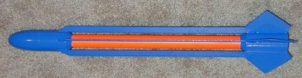
- STOP! Weird as it sounds, now is the time to finish, smooth and paint the inner tube section. I masked the upper and lower BT60 tubes at the transition and painted it Florescent Orange (Krylon). I didn't worry about getting paint on the transitions.
- Now assemble the fins to the rocket. I applied (1) Cooling Fin and (1) Main Fin at a time. Once all the fins are attached use you favorite fillet glue and method. I used wood glue for the entire assembly process.
- Push the Kevlar® Tether through the motor tube and up through the 24mm tube. Attach the Big Bertha's elastic to the Kevlar® and tie the elastic to the Nose Cone.
- Cut the center section our of the provided Parachute. Attach the Parachute to the Nose Cone. You will need to fold the parachute in such a way that it will fit into the 24mm tube as there is not enough room for it to fit in the upper BT60 section.
- Cut the Big Bertha provided launch lug in half and place 1 against a Cooling Fin on the top section and the other against the same Cooling Fin on the lower section.
- CAREFUL! You may have noticed that the Cooling Fins are "flexy" both back and forth and up and down. Don't squeeze them. Try to handle the rocket from the top or bottom.
- Now carefully work masking paper (I use computer paper) in between the Cooling Fin gaps and pull it very tight to protect the Orange finish of the 24mm tube. Expose the transitions. Use tape as needed to keep it held tightly in place.
- (22) Finish and paint the rocket. Dark Navy Blue (Krylon) is what I used. I regret not spending more time on my finish, but it was supposed to simply be a prototype.
Before I get into the flying of the Mercury Transport, I want to discuss a new finding for me about RockSim Free Form Fin Design. What I found is that when you go into the Free Form Edit page the point at "0, 0" and the farthest point to the right at "x, 0" are set. In other words the "0" on these two points is the established base line and are not changeable in RockSim. If you go ahead and draw out your fin pattern with the right-most point remaining as the "x, 0" then the fin will "touch" the body tube for the entire length of the root edge. In the Mercury Transports case, the fin spanned across the two different diameters of the tubes and therefore this made the root edge conform to the inner tube as well as the outer tube.
Please excuse my use of bright green on the fins here, it is simply to show the difference.
My design was for it to "bridge" the inner tube, not touch it. To make this work, I had to move the right-most point to be the second point from the left (in my case "0.5, 0"). The third point from the left had to be right above this point (in my case "0.5, 0.001"). By setting this to be "0.001" on the y-axis I was able to create the "bridge". After spanning the inner tube length including transitions I had two points again. One was at "14, 0.001" and the other right below it was "14, 0" which brought the fins root back into contact with the lower tube section.

What difference does it make? Major! The position of the CP with the root touching made the rocket appear, by calculation, to be unstable or marginally stable. With the fin true to design the rocket, by calculation, was over stable. RockSim calculations still had the CP on the rocket, while Barrowman had the CP way off the back of the rocket. Flight proved the stability of the design!
FLIGHT/RECOVERY:
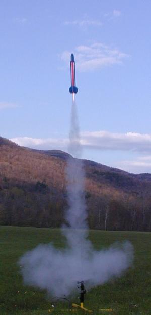 My first flight was on an Estes B6-4. It was absolutely perfect
and I can't describe it any differently. Stable and straight. It is a little
heavier model so the lift-off is not lightning fast allowing you to enjoy it.
At apogee the rocket seemed to hang parallel with the ground and just as it
appeared to stop and start down ejection occurred. The 'chute opened and it
descended safely to recovery.
My first flight was on an Estes B6-4. It was absolutely perfect
and I can't describe it any differently. Stable and straight. It is a little
heavier model so the lift-off is not lightning fast allowing you to enjoy it.
At apogee the rocket seemed to hang parallel with the ground and just as it
appeared to stop and start down ejection occurred. The 'chute opened and it
descended safely to recovery.
The second flight was on an Estes C6-4. Again stable and straight, just higher. At apogee it again was parallel to the ground when ejection occurred. One panel on the plastic 'chute stuck to itself causing less than full 'chute opening. That was okay because it was a little windy and this thing drifted down the length of the field. While reloading the 'chute I squeezed the Cooling Fins a bit too hard and cracked one at the attachment to the upper tube. Not broken through.
The third flight was back on the Estes B6-4 for another repeat of the first flight. This time my 'chute got tangled in my heat shield and did not open. Recovered with no damage.
I place the rocket in my box, satisfied with three great flights and I had three perfect lift-off pictures. As I headed back to the car I heard a crack of one of the Main Fins as I had squeezed the box a bit too hard. The fin was not broken completely off though.
 I repaired the two
cracks using CA. I lost, or rather my computer ate, my three launch pictures so
I was disappointed.
I repaired the two
cracks using CA. I lost, or rather my computer ate, my three launch pictures so
I was disappointed.
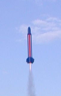
The next day my son and I ran out to do a single flight for the sole purpose of getting a flight picture. Got it on a B6-4 for a repeat of the first flight's performance.
SUMMARY:
The Mercury Transport has inspired me to press on with my 4" / 2.6" / 4" version. Can you scale up a rocket without impacting CP/CG relationship? Read Apogee's Newsletter Issue 80.
I would suggest that you strengthen the fins by CA'ing or a light paper cover. Whatever your favorite method is. Other than that, I think it is a nice rocket and would love to hear and see any experiences that you have building and flying this design!
Other Reviews
- Scratch Mercury Transport 18mm By Shane Tunkin
( Contributed - by Shane Tunkin) Brief: After reading about the unique fin design of the Mercury Transport in an Apogee Components newsletter, I thought this would be a great project and something to get my teeth into, to become a better rocket builder. Using the original EMRR design brief I worked out that I could find or build all the parts needed. My previous rocket projects had ...
 |
 |