Scratch MicroMaxx Mega Pad Original Design / Scratch Built
Scratch - MicroMaxx Mega Pad {Scratch}
Contributed by Carl Tulanko
| Published: | 2010-08-18 |
| Manufacturer: | Scratch |
Brief: Construction: The frame was easily constructed using the materials listed above. Also note you could make your own using a large round seat and 3" x 3/4" circular bulkhead plates instead of the “square” design I used…the sky is the limit. The hard part was coming up with a modular design for the pads and electronics. I settled on using DC power jacks in the base and plugs on each pad. Some 1/4" stainless steel rod was used opposite the plug as an “alignment” pin for each pad. Gold coated fuse tabs were cut and used for igniter contacts and I used some #2 hex head aluminum screws to mount each tab. The tops of each pad were covered with a piece of sheet aluminum I cut from a larger piece I got from the hardware store. Aluminum and Pine were used because of their ease to shape and cut. As far as the stainless pins go, I cut them from a couple of stainless “T” handles that were attached to a pack of ten “Remove before Flight” flags I won on the ROL Auction last year; I always recycle and was able to get about 3 pins per handle, each about 1" long. When finished, I had tons of pads all built and kept one master block of wood with holes drilled in case I wanted to make more later down the road. Power jack locations were routed in the bottom of the white shelf board and 12 gauge wire was run throughout. I designed the board for 5 active pads in parallel at one time, the fifth pad using two “posts” for cluster hookup. What is even nicer and an afterthought was, since the pad electronics were to be built from my HPR design, the “binding posts” at location five could also serve to launch HPR rockets directly from the pad, or the “binding posts” could be directly hooked into someone else’s launch controller and the MMX Mega Pad could be controlled by a club launcher. Once finished with the power jacks, four additional locations were drilled along the right side of the board for pad storage. The Plexiglas was epoxied to the 1" furring strips and this bottom “cover” was screwed into the bottom of the main pad board. Flight: Summary: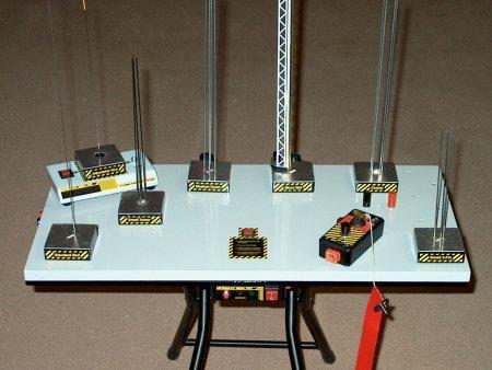
I have been flying MicroMaxx rockets with my kids for a long time now, and through our endeavors, we have made many improvements in certain areas pertaining to the MMX line. One of the first changes we made was to the launch pad/controller; the controller with a 9V battery was barely adequate for launching anything consistently, so we switched to using my homemade HPR single launcher and adapted the pads for this controller; it made a BIG difference! Something else was still missing though…I wanted a launch pad for all seasons, available for launching scratch or kit rockets not limited to the MMX launch rod. In addition, I wanted a pad able to supply enough current for clusters, along with the ability to “Drag Race” my models. Finally, it had to be elevated or provide an easy way to install the igniter in the motor prior to launch; crawling on the ground trying to get the rocket down over the igniter installed in the Quest Pad was getting old. For these reasons, I came up with what I feel is real close to the “Ultimate” in MicroMaxx launchers…I call it the “MicroMaxx Mega Pad!”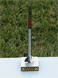 The concept originally started out as a small wooden chair, available at most stores for under $10. However, I wanted something bigger with the capability to store extra pads. Eventually, the chair I purchased was stripped of it’s back and seat and used for the “Legs” of the Mega Pad. I finally settled on a piece of 1’ x 2’ white shelving board, available at any hardware store. The design had also incorporated a bottom cover plate, made from 1/4" x 1" wood furring strips and a piece of Plexiglas, so I picked up two pieces of 1/4" x 3", each 24" long and would cut 1" strips from them. While I was still at the hardware store, I saw several pieces of Plexiglas in the “cutting” cage and one of the employees found me a piece, cut it to 12” x 24” and marked it “Scrap”…which in rocketeer terms means free! Finally, I picked up a three foot section of Pine 1 x 3 to make the pads. Total investment in wood, under seven dollars.
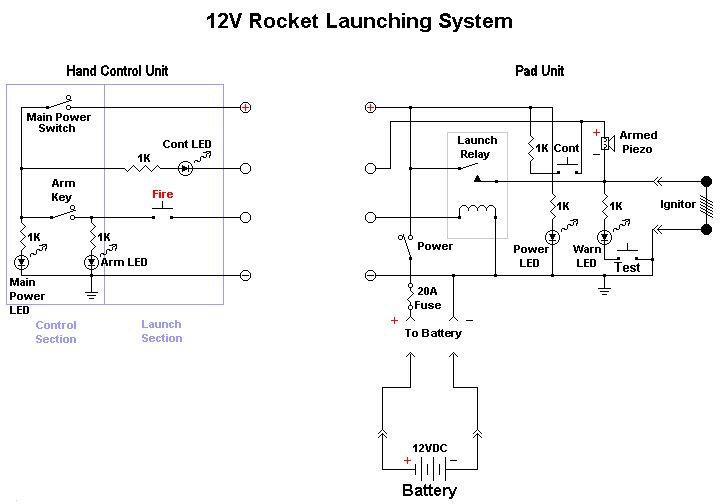
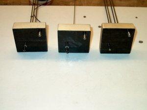 All electronics parts, with the exception of the RJ45 jacks, were obtained from my local Radio Shack and were used exclusively throughout the design. The pad controller uses a 30 amp relay to directly switch battery power to the igniter. Power is supplied to the pad unit via an automotive battery; alligator clips with two 8 gauge wires connect to the battery, while the other end plugs into two banana jacks on the left side edge of the board; the pad controller in turn supplies power to the hand unit. This path is protected with a 30 amp glass fuse, in case of accidental shorts. Also, a test button is incorporated into the Pad Controller to test the relay for shorts (welded relay contacts) prior to hooking up an igniter…a very nice safety feature. Power and Warning indicator LED’s are located on the front of the Pad Controller, the Fuse is on the left side, the 30 amp relay is in the rear and an RJ45 Networking Jack is located on the right. The 8 pin RJ45 jack is connected to the hand controller using the center four pins via a standard flat phone cable and plugs. On distances exceeding 100', full eight conductor network cable is used to “parallel” wire pairs for the four control wires, which decreases loss in the cable due to it’s length. All of this was designed integral to the electronics. The pad also has a piezo alarm for continuity, along with a continuity test button. There are several additional integral features designed in the background for testing and troubleshooting the units, but these will not be covered in this article.
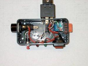 The Hand Controller has a power switch located on the top left side and indicators on top include LED’s for Power, Continuity and Arm. The safety key switch was purchased from Aerocon, a great source for these items, and I have used them on my L3 before with great success. A momentary pushbutton is used for launch and the four basic control wires run to a RJ45 jack on the top of the hand controller. The four wires supply 12 volts positive, 12 volts negative to the hand unit, along with continuity and fire to the pad controller. When powered on, a green power LED lights as does a yellow continuity LED as the unit checks for continuity and the piezo beeper can be heard at the pad. Turning the “ARM” key switch causes the red Arm LED to flash throughout the remainder of the launch sequence. When the fire button is depressed for launch, the beeper is bypassed and the igniter fires.
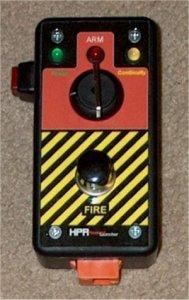 The pads themselves are very modular and allow you to build a “fleet” of launch surfaces; my pad types include a small tower, medium tower, large cluster tower, standard Quest two position rod, adjustable rod, 3 fin tower, a Rail with Tower and a small cluster tower. The possibilities are endless and allow you to try all different kinds of launch methods; rods are no longer a must as I have had great success with the tower pads. Using towers allows you to now worry about installing a launch lug and maintains a more realistic appearance for those “scale” models. 4-40 control rods are used for towers, while a rail was custom made from plastic bridge material and a square brass piece of tubing. For rail buttons, I used HO racecar track pins found at most hobby stores; the pin side was epoxied into the model.. The bottom of the pad has a 1/4" stainless alignment pin on one side and the DC power plug on the other. A flat bladed screwdriver is used through the bottom to easily push out used Quest igniters. In addition, the contacts can be cleaned and tension can be adjusted before insertion of the igniter.
 The best part though is rocket prep. I built a small “staging” stand that holds one modular Pad as I insert the igniter and install the rocket, all while I sit at my prep table. The Pad and rocket are taken out to the launch table assembled together, then plugged in an empty location and ready to go…it’s that easy! No more crawling on the ground, fighting with the igniter trying to get it installed. Moreover, I have incorporated a “Quick check” continuity tester built in to the prep/staging stand, so you know you have continuity before you take the pad to the table.
In summary, the MicroMaxx Mega Pad is a great project to build and a blast to use. After building it, I have a hard time trying to remember how we used to launch them. The guys at our local NAR club also enjoy that pad and it is there at all the launches I attend. Also, the pad has encouraged me to build several scratch models, which would never have come to pass if I was still using the old system. I have included schematics and pics, along with a LINK to my album containing step by step build photos. Also. you can send an email if you have any questions regarding the pad design or construction; as a matter of fact, I still have a few sets of labels for the pad and hand controllers that are printed and free to the first couple users. In the meantime, I will try to get a parts list together for the pad and provide a link to the labels for each controller. If you decide this is for you, go ahead and build one of these Mega Pads…you will not be disappointed!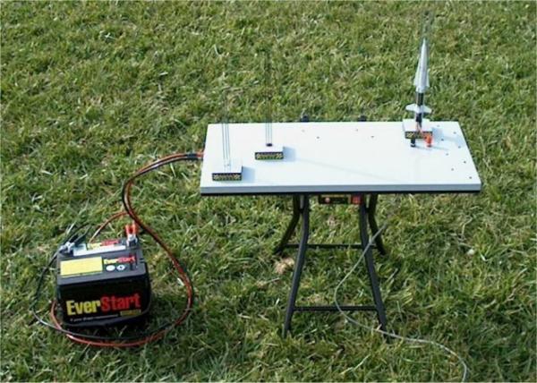
 |
 |