Scratch Moonship Original Design / Scratch Built
Scratch - Moonship {Scratch}
Contributed by Geof Givens
| Manufacturer: | Scratch |
Brief:
Imagine steering your own Moonship beyond Earth's atmosphere while you chart a
course to the moon and your sweetie is in the galley fixing up some chow. When
you reach the moon, you'll meet your pals for a fun-filled afternoon before
returning home to finish your schoolwork. Yes, it's 1955 and the age of space
exploration is here at last! Within a few years moon trips will be as common as
the modern phonograph and within the reach of most American families, but until
then you can build your own Moonship model featuring engineering marvels
certain to be seen on real moonships within the decade!
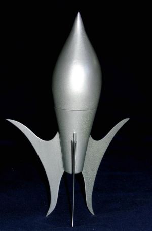
This is a retro-futuristic scratch model for 18mm motors designed with aesthetic inspirations from both art deco and 1950's sci-fi. It stands 12" tall. The body is 9" tall with a maximum width of 2.9", for a stubby ratio of 3.1:1. It is the first scratch model I designed on paper, but I didn't build it until much later because of the likely difficulties in construction and making it stable. After stumbling upon the Rocket Formerly Known as Black, I was inspired to attempt construction.
Construction:
The rocket is made from a large custom balsa nose cone, a balsa boat tail
intended for V2s, a complex balsa framing for the lower body, and basswood
fins.
The parts are shown in the first picture. They include:
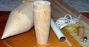
- Shape #7 custom nose cone from Balsa Machining Service (specs: M=.25" A=1.625", L=3.125" Q=2.9" I=2.719")
- CENV2BT boat tail from BMS
- 3" length of BT-20 tube
- 1" length of BT-60 tube
- 1/16" x 4" x 24" basswood sheet
- 1/4" thick balsa for ribs and lug mount (1" x 24" plank should suffice)
- recovery apparatus (screw eyes; shock cord/Kevlar®; parachute)
- launch lug
- 1oz lead weight
- 6+ inches of 3/8" hardwood dowel
- 3" x 3" square of scrap lumber, at least 1/4" thick
- power drill
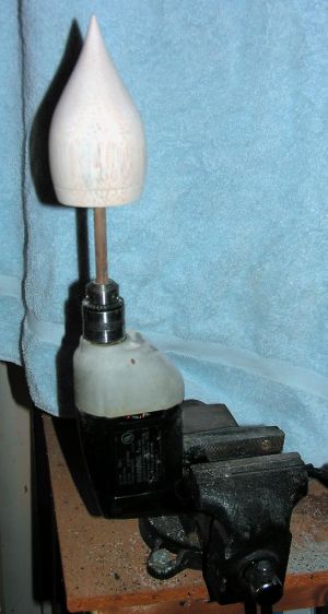
The custom nose from BMS has a straight conical shape with cylindrical base and shoulder. First, I cut a 3/4" thick pine square with edges exactly matching the diameter of the nose cone shoulder. I drilled a 3/8" hole in the exact center of this square, and a somewhat larger hole in the center of the nose cone. Next I threaded a 3/8" dowel through the pine block and glued the dowel (not the pine block!) into the nose cone hole, keeping the pine square flush against the nose cone to ensure exact centering and plumb. When the glue was dry, I slid the pine square off the top of the dowel. Then the nose cone and dowel assembly could be mounted in my power drill. This allowed sanding the nose cone to my desired shape, using a template from my plans. Finally, the dowel and glue were gouged out of the nose cone base, and the nose cone was hollowed out using a drill, knife, and sandpaper. A short piece of BT-60 tube glued inside the nose cone provided a smooth fit for the tail portion.
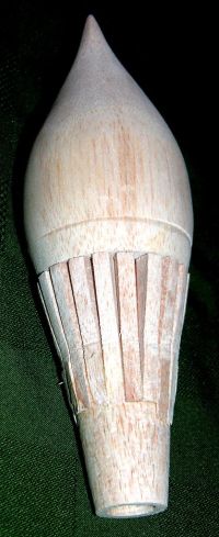
After dry fitting the boat tail into the nose cone, I fashioned a set of balsa framing ribs (intentionally too big) and glued them around the entire boat tail surface. Since the boat tail is somewhat conical, the ribs do not parallel each other: they taper together slightly towards the tail. Then I sanded the ribs down to nearly the desired size and shape, then filled the gaps with Elmer's Fill 'n' Finish. With a series of additional sanding and filling iterations, I eventually got the whole unit appearing as one smooth shape. One more round of priming, sanding, and filling rough spots yielded a good finish.
 By comparison,
the fins were easy. Compared to my original plans, I ended up exaggerating the
size of the fins and changing their shape somewhat to move the CP back more. I
always seal and sand before attaching fins. Cutting the curves and pointy ends
in the basswood required care, and I had to glue back a couple of broken tips.
Fin edges were gently rounded. The fins points are so sharp that I actually
stabbed myself once during painting and drew blood.
By comparison,
the fins were easy. Compared to my original plans, I ended up exaggerating the
size of the fins and changing their shape somewhat to move the CP back more. I
always seal and sand before attaching fins. Cutting the curves and pointy ends
in the basswood required care, and I had to glue back a couple of broken tips.
Fin edges were gently rounded. The fins points are so sharp that I actually
stabbed myself once during painting and drew blood.
Recovery is by parachute. I attached the chute to the shock cord very close to the bottom body portion in hopes that this would soften the landing for those fragile fins by allowing the heavier nose cone portion to land first.
At the last moment I realized I had a significant launch lug problem due to the shape of the fuselage. I had to fashion a standoff so that takeoff would be vertical and the rod wouldn't interfere.
Swing tests were surprisingly good. It seemed that only 0.5oz nose weight might be needed, but I used 1.0oz just to be sure. With this, the finished rocket weighed 4oz. The CG is about 1mm below the seam where the upper and lower rocket body portions meet.
Finishing:
From initial conception onwards, this was always going to be a pure silver
rocket in the "Flash Gordon" style. I covered the silver with two
coats of gloss. It was off to the launch site.
Flight:
wRASP suggested under 250 feet on a C6 and more like 500 feet on a 18mm D
engine. I loaded a AT D13-4W RMS (my first RMS ever) and the kids pressed the
button. My wife jumped and let out a little scream as the rocket roared off the
pad. It was so much louder! I'm going to love these motors.
Ascent was strange. The rocket seemed to veer downwind off the rod with a corkscrew ascent. As it continued upwards, the corkscrew tightened and the spin diminished. However, the flight began arcing downwind. The final moment of the boost was nearly horizontal, but the small silver rocket was so far downrange that it was difficult to see. I wasn't sure if the parachute ejected and didn't really see the landing although I spotted a brief glint of something which gave me a good read on the direction to walk.
I found the rocket a good quarter mile downrange and everything became clear. The launch lug was literally ripped off the rocket. The takeoff had been completely without guidance! Sure enough, when I got back to the launch pad, the lug (with some balsa standoff shreds) was still at the bottom of the rod. I slid it off for later repair and cleaned the rod. A couple shroud lines broke on ejection, explaining the recovery mystery as well as cracking off one fin on landing.
Considering the launch lug debacle, I am pleased with the flight. I believe the design is stable because it recovered from a no guidance takeoff and improved its flight characteristics during the boost phase. I'm not sure about the arcing at the end of boost, but it was not much worse than other short stubby rockets. Overall, the D13-4 gave a much faster and higher boost than expected or simmed: probably 600 high on its arcing trajectory which might have been nearly 1000 on a straight boost. I'm going to glue the fin back on, improve the lug mounting, and shoot her again!
 |
 |