Scratch Mystery Rocket Original Design / Scratch Built
Scratch - Mystery Rocket {Scratch}
Contributed by Dave Sutter
| Manufacturer: | Scratch |
I wanted to build something. Something different. Something very different. But what? I had been reading G. Harry Stine's Handbook of Model Rocketry, and was thinking about stability. You need the weight up front, and the fin area out back. The motor is definitely the heaviest part, so it made sense to have that up front. But, you can't just stuff it way up inside the body tube because of the Krushnic Effect. So... what if it didn't have a body tube? What if I attached the fins some other way...? So, I present to you:
 Mystery Rocket
Why the "Mystery Rocket"? Well, because I built it in secret from my wife. I wouldn't let her see it at any stage of the construction. I had to think of something to call it when she asked about it, but I didn't want to use a name that would give it away. What can I say, the name just stuck. In fact, the first time she saw it was when I "unveiled" it at the launching field for it's first launch. As predicted, her first comment was "Is that even going to work?" I get that a lot.
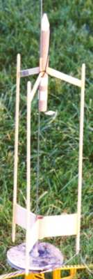
The photo above was taken that first day. I hate painting, so I wasn't about to paint it until I knew it flew. Don't mistake my hate for painting with laziness, though. You'll notice that all the edges are rounded, and, though you can't tell from the photo, the fins are sanded to an airfoil shape. It's built with care, it's just not painted.
There were three big questions running through my mind before that first launch:
1) Would it be stable? I was pretty sure it would be just fine, with all the weight up front, and all that fin area way out back. Now, I'm convinced that it's actually quite overstable. But, this was my first "odd-roc", so there was that little inkling of doubt in the back of my mind.
2) Would it hold together? This was really my biggest concern. It's all just plain old yellow (carpenter's wood) glue construction, and those front struts have quite a load on them. There was only one way to answer this question...
3) What size engine should I use? I don't own a scale, so I have no idea how much it weighs. I figured I'd start with a 1/2A6-2 and work my way up.
Well, there should have been a fourth question, but I was so convinced that it wouldn't be a problem, that I really didn't give it much attention... Would the motor exhaust burn the lower structure?
Well, you can read the full launch report of that first launch, but I'll tell you now that the answers are Yes, Yes, At least a B6-4, and Yeah, a little bit, but not too bad.
Update 1997 Nov 15
Before the second launch, I painted it. I wanted the lower structure to have some resistance to scorching, so I used some flat black exhaust system spray paint (good to 1500 F) for the body tubes. I then painted the vertical struts day-glow orange (aka International Orange) for contrast. I didn't use any masking tape... I just let the two colors blend naturally in the middle of the fins and upper struts.
Here's a link to the second day's launch report for this rocket. Here are photos from the second launch day: launch photo #1, launch photo #2, recovery photo, and a close-up of it in flight. The close-up photo shows why there's some scorching of the lower structure, eh?
Want to build one yourself?
NOTE: Read all instructions before beginning so that you have some idea of what I'm getting at with each step. Feel free to modify the construction in any way you see fit. I only ask that if you do something cool or practical, please write to meand tell me about it! Note that at the bottom, I have a list of alternatives to the construction I've detailed here. Of course, I take no responsibility for anything you do.
Parts List:
- BT-20 body tube, 9" long
- Short conical plastic nose cone PNC-20
- 3/16" wooden dowel, 36" long for the vertical rods
- 1/2" wide balsa strip, 10" long
- 1/16" thick balsa sheet, enough for (3) 2"x3" rectangles
- thin 100 pound test line, 12" long (I used braided black Kevlar® fishing tackle line)
- shock cord, 18-24" long (I used 1/16" round elastic cord, 24" long)
- small split ring (available from fishing supply stores)
- 12" plastic parasheet & shroud lines (I used a standard Estes chute, with a size 7 snap swivel)
- (2) 1/8" diameter launch lugs, 1.5" long (I used plastic soda straw wrapped with masking tape)
- EB-20 engine block (I used a piece of expended 18mm engine casing)
- engine retainer hook (I used a standard Estes 70mm hook)
- masking tape
Construction Supplies:
- Typical stuff (hobby knife, pencil, ruler, table, brain, eye-hand coordination, etc)
- Aliphatic resin glue (aka Yellow glue, aka Carpenter's Wood Glue)
- 3/8" wooden dowel, at least 24" long, preferably longer
- two expended 18mm engine casings with the clay nozzle knocked out
- something to hold the 3/8" dowel about 3inches off the table (I used a rocket cradle)
- 1/16" drill bit (or any relatively small drill bit or other boring device)
Construction Steps:
- Cut a 2" section off the 9" body tube. The 2" piece is the lower body tube, the 7" piece is the upper body tube.
- Cut out the three 2"x3" fins. Sand them to an airfoil shape, apply sanding sealer, and sand them smooth.
- Cut the three struts from the 10" balsa strip. To make sure that they extend exactly the same distance (3") as the fins, I placed a fin on top of the strip so that the strip ran diagonally across the fin, and marked the strip with a pencil. The result was that the strips came out with about 3 1/4" of both leading and trailing edge.
- Cut the 3/16" wooden dowel into three 18" pieces. Sand the ends to a pleasing rounded shape.
- Glue in the engine block.
- Mark the upper body tube 65mm from the bottom, and cut a 3mm wide slit in the tube there for the engine hook. Place the top of the hook in the slit and tape on the engine hook.
- Use the 1/16" drill bit to bore a hole about 1/2" from one end of one of the forward struts. This is the shock cord mounting point.
- Attach the fins to the 2" section of body tube just like normal fins.
- Attach the forward struts to the 6 7/8" section of body just like normal fins. I put the bottom edge of the struts about 3" from the back end of the body tube.
- Ok, here's the tricky part. Slide the two expended 18mm engine casings (with the clay nozzles knocked out) onto the 3/8" wooden dowel. Now take the upper structure and slip it over one of these engine cases on the dowel. Put it in just like a normal engine. Now take the lower structure and slip it over the other engine casing. Position the two structures about 10" apart. Now rotate one of the structures so that the fins line up with the struts. I just used my eyeball for this alignment, but you could try using a straight stick to help.
- Now place the whole thing onto the rocket cradle (or wood blocks, or whatever you want to use that will hold it all about 3" off the table top). Rotate the dowel so that one fin/strut pair is pointing straight up. Again, I used my eyeball, but if you have a level, go nuts with it. Glue one of the vertical rods to this fin/strut pairing so that it extends about 2" below the fin. Let it dry completely. Repeat for the other two rods.
- Now glue on the two launch lugs, putting the lower one in the fin/body tube joint, and the upper one in the corresponding strut/body tube joint. For best results, align the bottom of the lower launch lug flush with the bottom of the lower body tube so that it's recessed 1/2" from the top of the lower body tube. This will help protect it from the engine exhaust a little bit.
- Glue the nose cone base into the nose cone, if necessary.
- Assemble the parachute, and tie it to the snap swivel.
- Tie the small split ring to the elastic shock cord, about 4" from one end.
- Tie the end of the elastic shock cord near the ring to the base of the nose cone.
- Tie the other end of the elastic shock cord to the thin 100lbs test line.
- Tie the other end of the thin 100lbs test line through the small hole you drilled in one of the struts.
- Clip the snap swivel attached to the parachute to the split ring.
- Stuff the parachute, elastic shock cord, and as much of the thin 100lbs test line as possible in the top of the top body tube. The nose cone may be a moderately tight fit since the thin line is in the way, but it wasn't too tight for me (the ejection charge still blows it off easily). If it's really tight, you can try to cut a channel out of the plastic of the nose cone shoulder.
- Well, now you should have something that looks, more or less, like the picture above.
- Feel free to paint it however you like.
Alternative Construction Ideas:
If you want to be able to use 24mm engines (for D, E, and even F power), just substitute BT-50 tubing for the BT-20 tubing, and a PNC-50 nose cone for the PNC-20 nose cone. I'll probably try this soon, just to see if it holds together.
If you're worried about the struts holding onto the vertical rods with that much power, cut or drill slots in the rods and use "through-the-rod" strut attachment ;-). If you're worried about the struts holding onto the body tube you have two options. First, you could switch to using a body tube for the upper structure that is larger in diameter than your engine (say, BT-55 or BT-56 tubing), and use "through-the-wall" strut attachment. Second, if you still want to use a minimum-diameter body tube, drill two or three small holes in each strut, very near where they attach to the body tube, and then thread some of that 100lbs test line through the holes and around the body tube, to literally tie the struts together. Add a little epoxy to stiffen and strengthen the line, and you've got some very solidly attached struts, I suspect.
On the other hand, if you want to build a scaled down version to use 13mm mini engines (or 10.5mm micro engines), you'll probably have to find something much lighter than the 3/16" dowel used for the vertical rods, in addition to using small body tubes and smaller nose cone. I might try this using bamboo cooking skewers for the vertical rods.
If you're worried about the scorching of the lower structure there are two routes you can take. The first is to put more distance between the engine and the lower structure. You could easily put 2 more inches between them just by attaching the fins and struts farther apart on the vertical rods. Or you could go with longer vertical rods. But be careful about adding too much weight this way (hardwood dowels aren't light). Or you could the struts at more of an angle or mount them lower on the upper body tube. All these mods together could easily buy you 5 or 6 more inches of distance there (and could change the look of the rocket significantly... possibly for the better).
The second (and probably more elegant) solution to the scorching problem is to simply use a much larger piece of body tube (like BT-60 or BT-80) in the lower structure. That way, the hot engine exhaust should mostly just blow through the tube, rather than onto it. Be forewarned, however, that this will result in significantly less fin area, so it might become unstable by making this modification. If you're afraid of that, just make that piece of body tube and the fins taller to increase their total area. I'm pretty convinced that this thing is very over stable as it is now, though, so I wouldn't worry about it too much.
If you're just worried about melting or burning the lower launch lug, try epoxying a couple of small metal split rings to the fin/body tube joint to form the launch rod guide, instead of using a traditional launch lug. Don't stress too much about it, though, because I continue to launch the original, using just the upper lug, and it works just fine.
Update 1997 Dec 7
Unfortunately, the Mystery Rocket crashed and broke into several pieces at the 1997 Dec 7 launch when I tried to see how well it flew in the wind. It wasn't the wind's fault, though; I should have used something bigger than an A8-3 engine. The rocket got turned over before ejection, and fell into the chute, tangling the chute, and causing the crash.
Update 1997 Dec 12
I glued it all back together, and reinforced the new joints with strips of silk span. It held up wonderfully.
Update 1998 Feb 7
This rocket was, in some small way, inspired by that very first liquid-fueled rocket that Robert Goddard launched.
| Description: | Front-mounted engine, three-shaft experimental rocket. See photo. |
| Purpose: | To boldly go where no rocket (that I've seen) has gone before. |
| Motors: | Well-flown on B6-4 and C6-5. Too heavy for a 1/2A6-2 or an A8-3. |
| Max Altitude: | Not sure, let's say 300 feet on a B6-4, and maybe 500 feet on a C6-5. |
| Length: | About 22 inches. |
| Diameter: | Tubes: BT-20 Top tube is 6 7/8" long, bottom one is 2" long Total diameter: About 5 1/2 inches. |
| Weight: | ??? |
| Recovery: | 12" parachute |
| Nose Cone: | Short cone, plastic |
| Payload: | None |
| Fins: | 3 forward struts, 3 1/4" x 1/2" balsa 3 rear fins, 3" x 2" balsa |
| Notes: | Tons-o-fun!!! |
| Skill Level: | Oh, about 3 |
| Part Number: | None |
| Price: | Oh, probably about $7 in parts. |
 |
 |