Scratch Outland'ish Original Design / Scratch Built
Scratch - Outland'ish {Scratch}
Contributed by Brad Shea
| Manufacturer: | Scratch |
Brief:
When I opened my box of parts, I was overwhelmed. I saw a number of people crying over their relatively lackluster boxes - but my box seemed like a cornucopia of great parts.
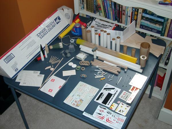
I was bowled over and amazed at the sheer number of ideas that were possible to build using these parts.
I literally must have done 100 RockSIM designs and variations trying to hone in on a design that I liked AND that appeared to be stable and that I could actually build. On each design I know I ran multiple simulations on various engines over a dozen times. Eventually it came down to two basic designs. One was essentially a long tapering rocket.
It was thick and large at the bottom and gradually over a series of three transitions became smaller and smaller - with one twist. That rocket used an Estes Outlander nosecone as part of the tail assembly as the first stage (tumble recovery) of a 2 stage system. The Rocket would have ended up with a skirt fin (funnel shaped) and fins. But I couldn't shake the feeling this was a little too boring. So it was time to go back to the drawing board. I then experimented with the partial Outlander nose on the front of the rocket.
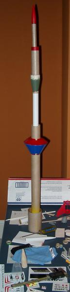
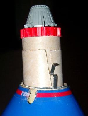
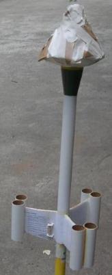
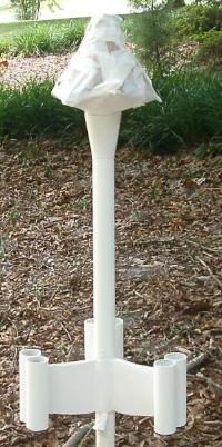
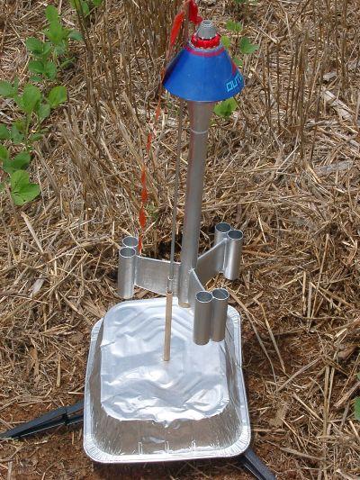
This made simulations easier - there was no longer a need for nose weight to make things stable. On the other hand - it was hard to determine how to simulate the rocket. In addition, the partial nose didn't have anything in the front. I decided to build it and use the space for an electronics bay. As I began to simulate various fins I realized my only large fin-stock was air foiled like a glider or airplane wing. This asymmetric airfoil could work and it would mean that the rocket would spin if I played my cards right. The spin induced might even add a little extra stability - which could be needed due to the potential for the nosecone to blank the fins in its wake. As things came I decided that pods on the end of the wings were a necessary part of the way this rocket would look. I tried building various pods in RockSIM and on the table in mockup's - but nothing was working until I stumbled into the idea of using TWO 24mm tubes together at the end of each fin. This was partially required because I am lousy at cutting the wood perfectly at a 90 degree angle so the pods didn't want to be quite perpendicular to the main body - and partially because it allowed me to try placing BT5 body tubes out on the ends of each fin for potential clustering. The BT5's looked awful... and they went the way of the Dodo. Thus the design for Outland'ish was born... Outland'ish is an MPR rocket made using an Estes Outlander upper section as a nosecone. The idea was to create something that might have graced a 70's or 80's Omni cover. Something a little odd looking as a traditional rocket but still recognizable as a rocket nevertheless. The rocket's main attraction besides the big nose is the altimeter/timer bay built into the nose and disguised as a bit of space technology - perhaps a sensor or weapons array. Using this bay electronics can be flown in this lightweight MPR rocket. A spare engine hook is used to ensure that the altimeter bay is not lost. NOTE: Weight Listed is without motor or altimeter but with Parachute and altimeter bay in place.
Construction:
- BT50 (24mm) Tube: 1 @ 11.5", 6 @ 3.25"
- BT60 (1.6") Tube: 1 @ 3.25"
- BT55 (1.3") Tube: 1 @ 2.4", 1 @ 1.6"
- BT5 (13mm) Tube: 1 @ 1"
- Centering Rings: 2 @ BT55/BT5 (Cardstock), 2 @ BT55/BT20 (Cardstock), 2 @ BT5/BT20. 2@BT55/BT50.
- 2 Engine Hooks - D Sized
- 24" Plastic Parachute (Shroud Line Material @ 120", Avery Label Paper for tape discs)
- 29mm Red plastic part off old yellow rocket.
- Oddball cone from Sci-Fi plastic model.
- Used Printer paper for lamination of the fins.
- BT50/BT60 Balsa transition
- Estes Outlander Upper body - without nosecone tip.
- Portions of the Cardboard Shipping box for adapting the BT55 e-bay to the Bt-60 tube.
- Wood Glue
- Epoxy and Microballons
- Thick CA
- 1/4 inch LOC style Launch lug (1" long)
- 24mm Engine Block
- Short (< 25") Section of Kevlar Cord (from old rocket in the box)
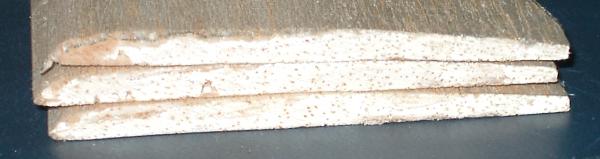
- 0.250 Thick Balsa - Air foiled like an AIRPLANE WING - NOT SYMMETRICAL - ONE SIDE IS STILL FLAT. Piece should be about 9-10" long and about 3" wide.
- Elastic Shock Cord material - 24-36".
Step 1 - Cut BT50 Sections:
Cut BT50 into appropriate lengths specified in the parts list above (see optional below before cutting.) The long BT50 section is the main body tube. The other short sections make up the pods on the ends of the fins.
OPTIONAL: If you want to have room to tape your motor to the tube during flights you will need a longer main tube. In this case cut the main tube 1/2 of an inch longer than specified in the parts list.
OPTIONAL: If you wish to use square fins you may need to adjust the length of the pods to allow them to be longer than the fins. This is not how I did mine so make adjustments as necessary.
Step 2 - Create Fin Pods:
Take two short sections of BT50 and wood glue these together (parallel) so that they form a twin tube that can be added to the end of the fins later. Place glue on one tube slightly thicker than you would use for a double glue joint and then press the two tubes together and slide them back and forth. Line up the top and bottom and then use rubber bands to hold the tubes lightly together. Inspect the assembly for excess glue and remove any that is built up if excessive. Set the assembly aside to dry. (TIP: I used wax paper to avoid messy kitchen table cleanup!)
Repeat this step for each pair of short tubes. You should end up with three (3) sets of two (2) tubes.
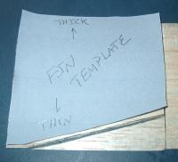
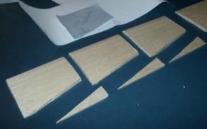
Step 3 - Cut Fins:
Use supplied fin template to mark and cut fins. If you have enough fin stock make a fourth fin "just in case" you ever need it.
Step 4 - Cut BT60 to Fit Nose:
Measure and cut a section of BT60 to the length specified in the parts list. The exact length is not actually very important as long as the tube section cut will go all the way through the Outlander body section and leave a small amount (maybe 1/4 inch) sticking out the back.
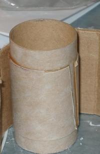
Step 5 - Fit BT60 inside Nose:
Gently roughen the plastic surfaces where the BT60 tube will contact the Outlander body section. Fit the BT60 section just cut in step 5 into the Outlander body section. Verify a good fit. Once satisfied with this fit, test fit the BT50/BT60 transition. If everything fits move on to step 6. If not stop and adjust things sanding as necessary to ensure that you have a reasonable fit.
Step 6 - (OPTIONAL) Drill Transition:
This step is only required if you use the nose to house electronics that will need access to the main tube for deployment. Center the BT50/60 transition on a drill press (if available). Using a 1/8th inch bit drill down the center of the smaller (BT50) side as far as the bit will reach. Most 1/8th inch bits will NOT reach through but will stop somewhere in the middle. Flip the transition over and center it again. Drill through and attempt to connect with the existing hole. If you have trouble you may need to up the size bit on one of the holes. Once you connect the two holes try passing the wires you plan to use through the holes. In my case my ematches were directly wired to the electronics - so I tested using those.
Step 7 - Attach BT60 to Nose:
Take the section of BT60 that you plan to place inside the Outlander Body tube. Partially insert the BT60 (about halfway) and stop. Using THICK CA (not regular superglue!) coat the inside edge of the top of the Outlander body section. Place the entire assembly upside down on wax paper and push the body tube into place. If you need to invert this and help guide it remember to not glue yourself to anything. CA will bond skin quickly!
Once the tube is in place use thin CA to go around the bottom edge and wick CA into the joint between the plastic and the tube. You may wish to also finish this joint with additional thick CA when the thin CA is "dry".
Step 8 - Attach Transition:
Coat the top of the BT60/BT50 transition with wood glue use enough to prevent premature seizing and insert this into the Outlander Body section so that the BT60 transition is glued to the BT60 tube inside the section.
Step 9 - Mark the Fin Locations:
Take the main body tube and using either a fin marking template or fin marking tool mark the location of the three fins. Once the locations are marked then use either an angle bracket, a fin marking tool, or a doorway to draw straight lines to help align the fins as they are placed onto the tube.
Step 10 - Attach the Fins:
NOTE: This step is written for flush mounted fins. If you have opted for the optional extra length main body tube please adjust by 1/2 inch to account for the additional length.
Take the root of one of the fins and use the standard double glue joint to attach it. This method requires that you place a thin layer of glue on the line drawn for the fin and the root edge. Let both of these partially dry then add a tiny amount of additional glue and press onto the rocket. The THICK part of the airfoil should go on so that it is farther from the end than the THIN part. If you are using the flush mount option the thin edge should be flush with the bottom of the main tube.
 Support this fin until it becomes strong enough to stand upright. If you have a fin jig like the Estes Fin alignment tool you can support it this way - otherwise simply hold it until firm.
Repeat this step for each additional fin until all three fins are solidly attached. The fins should end up 120 degrees apart just like any standard 3 fin rocket.
Step 11 - Fillet:
Find a way to support the rocket parallel to the ground (you may want to put the nose on to balance things for the time being.) Once the rocket is stable position it so that one fin is directly down and the others are in a "Y" position. Use wood glue along the surface of each fin/body joint in the bottom of the "Y".
Wait 30 mins or so depending on the wood glue until the glue skins enough that it will not run. Rotate the rocket 120 degrees and repeat. Keep doing this until all three sides are completed.
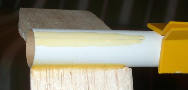
 Step 12 - Attach the Pods:
Time to attach the first pod to the fins. Lay out a sheet of wax paper, some nitrile gloves, some kind of mixing cup (paper works), and a mixing stick (popsicle sticks work well for this). Mix equal parts 5 min epoxy hardener and resin along with an equal volume of microballons making only enough to do ONE fin pod at a time. (See notes below) Take the epoxy and spread it into the valley between the two tubes that make up one pod. Keep the epoxy in the middle area where the fin will sit. Lay the pod epoxy side up on the wax paper and then take the main body and fins and push one fin into the epoxy holding the rocket parallel to the tubes so that the fin rises up vertically from the exact middle of the pod. (See picture). Hold this position until the epoxy sets enough that you no longer have to hold it. This should be in about 5 mins from the time you mixed it. Repeat the process for each additional pod until all three fins are completed.
CAUTION: Please use proper caution with the epoxy - nitrile gloves are higly recommended. Do not get any epoxy on yourself if at all possible. Epoxy allergies are cumulative and can strike after repeated exposure.
NOTE: If you have never used microballons be careful since these are easy to blow away or overstir until they are mixed in. Don't take too long since this is 5 min epoxy and the working time can often be less than 5 mins. If you are worried about this use 15 min epoxy for this step. If you do not use microballons you will need to add masking tape to hold the epoxy in place. This will also increase the weight since the microballons reduce the density of the epoxy.
Step 13 - Rear Engine Hook:
Traditional ways of attaching an engine hook will not work with the flush mounted minimum diameter motor tube design. However what I did should work for you reasonable well. Position the engine hook on the BT50 tube alongside one of the fins on the flat (not curved) side of he fin so that the hook portion is hanging off the bottom about 1/2 inch past the end of the rocket. Mark where the 90 degree bend at the top of the hook falls on the side of the BT50.
Cut a tiny slit perpendicular to the tube length so that the hook top can go through the side of the rocket. Fit this in place and use thick CA to hold the hook to the rocket. Mix up another small batch of microballons and epoxy and coat the engine hook and form a small fillet alongside the fin. This should hold the hook in place but we will be adding additional strength in another step.
 Step 14 - Engine Block:
Take the motor block and tie the Kevlar to it. Use whatever knots you are happiest with. A surgeons' knot is a reasonable choice - but there are plenty of options available online - Google animated knots if you are unclear what might work.
Use a thin stick long enough to reach from the rear to just past the motor mount section and apply wood glue in a circle up just past the top of the motor hook inside the rocket. Holding the rocket horizontal or slightly inverted take the Kevlar tied engine block and from the top using a long BT20 or other means - push the engine block down to where the glue and the top of the engine hook are. Invert the rocket fully and find a way to support it until the wood glue dries.
Step 15 - Recovery Harness:
Tie a small loop in the end of the Kevlar that hangs out of the top of the rocket. This is where the remaining shock cord will be attached. Again if you are confused about knots consult a knot reference like Animated Knots.
Step 16 - Laminate & Reinforce:
Take the fin template and cut out 6 paper fins from the printer paper. Overcut three of them slightly in the top to bottom direction to compensate for the airfoil. Use these larger ones on the curved sides of each fin.
Coat one fin surface at a time with wood glue and then press the paper fin onto the wooden fin. Position it and don't fret about any that hangs over the top or bottom. The excess will be trimmed with a hobby knife later when it dries. Once this has adhered move on to the next surface until all 6 sides are complete.
Next freehand create a square sheet that will fit from 1/2 of the way along the fin from the main body to the other fin 1/2 of that fin. Essentially this is like TIP to TIP fiberglass work but only going from 1/2 of the way along the fin and using paper and wood glue. This will cover the engine hook and the filets on the fins. Repeat for all of the fin/body pairs (3 total) until these are all reinforced in this way.
NOTE: You may wish to substitute cardstock for printer paper when making this as a non-contest rocket. Cardstock will be stronger than the printer paper and works in essentially the same way.
Step 17 - Launch Lug Placement:
Using a 1/4 inch rod line up the location needed for the launch lug so that the lug is on the flat side of a fin close but not against the root so that it lines up with the hole in the Outlander body section. The idea is to have the rod parallel to the BT50 tube in both the horizontal and vertical directions. Mark the launch lug location so that the lug can be attached. Using Wood glue or Thick CA glue the lug in place. Later you can fillet this if it seems to need it. Take care not to put glue into the hole on either end to avoid making the launch lug too tight.
At this time you should also mark the location of the nose relative to the body so that you can always turn this back to this point. Mark with a thin sharpie for now and later add decals or other means of indexing this.
 Step 18 - Altimeter Bay Tube:
NOTE: If you are not building the altimeter bay you will simply glue this cover in place later and leave out the FRONT engine hook.
Take a section of BT55 and cut to two sections as specified in the parts list. The longer section is the main altimeter tube. The shorter section is only used to friction fit the tube in place. This short tube should be cut vertically apart and then glued onto the larger tube. Center the shorter tube so that an equal amount of the larger tube sticks out of each end.
Step 19 - Altimeter Bay Cover Cores:
Take a pair of BT55/BT50 fiber centering ring and two BT55/BT20 paper centering rings and two BT55/BT5 paper centering rings.
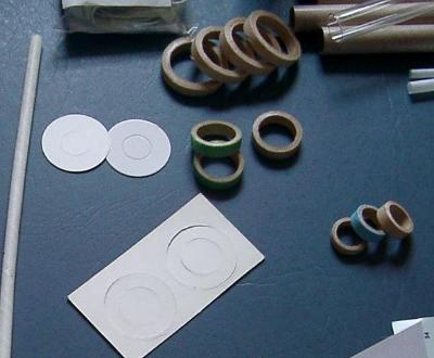
Do not punch out the paper rings. Take one of each of the three components and using wood glue glue these so that each ends up as a ring with one BT5 and one BT20 paper centering ring on the top / bottom of the BT55/BT50 ring. These will form the core of the top and bottom cover of the altimeter bay.
Step 20 - Altimeter Bay Front Cover:
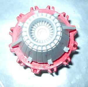
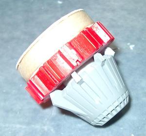
Using the short section of BT5 from the parts list. Test fit inside the space ship cone shaped nozzle. This should fit reasonable well already. To one end, add a BT5/BT20 centering ring. Fill the attachment area with thick CA and push the centering ring/BT5 back into the nozzle. Add additional CA to hold the centering ring to the BT5 from above. Once all of this has set - then you can add another BT5 to the opposite end of the assembly. Knock out the BT55/BT20 disk on one of the two covers. Coat the inside with wood glue where the BT5 disc is still in place. Coat the top surface with wood glue where the 29mm decorative ring will go between the nozzle and the cover. Coat the BT5 tube with wood glue above the BT5/BT20 ring so that when everything is assembled it will be glued in place. Push everything together so that the cover is assembled.
Step 21 - Altimeter Bay Sleeve:
Cut a 2.5" x 5" length of corrugated cardboard from the USPS box. The exact dimensions will be dependent on the exact fit/thickness of the BT60 and transition. Essentially you want a single layer of cardboard to fit down inside the BT60 and end up flush with the top of the Outlander Nose. This sleeve helps to friction fit the BT55 altimeter bay.
 Test fit the cardboard until it just fits without overlapping. Get the second engine hook ready and test fit it so that it points to the top of the rocket from inside the BT60 inside the Outlander nose with the hook positioned between the cardboard sleeve and the BT60. The sleeve should be on top of the small bent end of the hook that normally goes at the top of an engine. The hook should be placed away from the launch lug area if possible. Once this position is well known, take everything out and get ready to glue.
Coat the entire surface of the outside of the cardboard sleeve with wood glue. Roll this up tighter (but not tight) than the BT60 and position it and the engine hook in place. Use your hands to apply pressure outwards on the BT60 until the sleeve sets in place.
Step 22 - Altimeter Bay Bottom:
Take the other fiber ring with the two paper rings attached. Punch out both rings and add wood glue between them. Roll this around to coat the joints. Set aside to dry. When dry insert this ring into the bottom of the BT55 tube. Insert only slightly and ensure that the BT5 hole is face down. Coat the bottom ring (the BT5/BT55 side) with wood glue liberally but not so much that it will drip off. Place the assembly into the nose so that the Bottom Cover ends up against the top of the BT50/60 balsa transition. This should be centered and you should see the hole you drilled if you are using that optional finish step. Do not push too hard or the cover may become permanently attached to the BT55 - this is NOT what you want. Gentle pressure and then leave it alone!
Leave to dry. Once dry the BT55 should be able to be removed without pulling the bottom cover from the transition. This will act as a centering ring/guide when the altimeter bay is put in place in the future.
Step 23 - Screw Eye Placement:
Add a screw eye to the balsa transition on the BT50 side. Place this to one side if you have drilled the optional hole. Screw in once gently and then back out. Add thick CA to this hole and screw it back in. Set aside until the glue is cured.
 Step 24 - Altimeter Bay Final Fitting:
Put the top cover in place on the BT55 and by pulling the top engine hook back slightly verify that the altimeter bay will seat onto the ring inside the BT60 nose cavity. If anything is too loose add small amounts of tape or use CA to thicken the BT55. If you use CA use the THIN kind and wait for it to cure before testing the fit again. Generally this will swell the parts enough to cause loose fitting parts to be tightly fitting.
Step 25 - Recovery Harness:
Tie together the Kevlar® cord and the section of elastic. Tie the elastic to the screw eye. Again if confused about knots consult Animated Knots.
NOTE: For my build I had to use two different elastic cords to get enough length. Normally I avoid elastic and after the contest I will probably replace this will a longer section of Kevlar® or nylon.
Step 26 - Parachute:
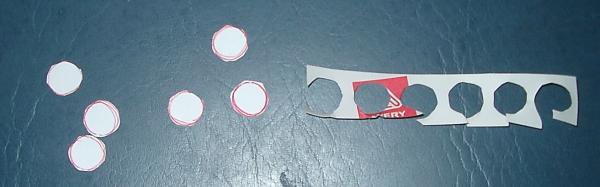
Obtain and use a 24" plastic parachute. For my contest rocket I had an Estes 24" chute and some shroud line material and avery label paper. The label paper makes a great tape disc reinforcement. Simply cut small round discs out (use a BT50 centering ring as a template).
NOTE: My shroud cord was taped with masking tape and by the time I got to it was quite sticky. I used Goo Gone and cleaned the line and then washed the line with soap and water and dried it.
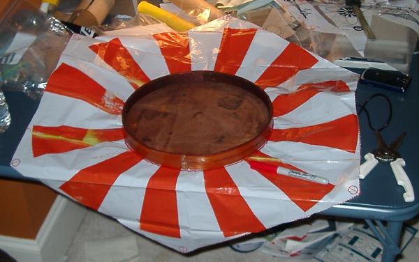
Cut out the plastic parachute from the sheet. In addition, cut out a 12" round section from the middle to form a giant spill hole. This is needed to reduce the size of the parachute to fit the 24mm body tube but also provides theoretically better stability and deployment.
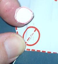 Divide the shroud line material into thirds and cut each into a section of shroud line. Attach each line to two adjacent corners on the parachute using the label disks and knots.
Attach lines to the screw eye directly to ensure deployment of this large parachute from the small tube. I would not normally go to this much trouble for some shroud lines - but this was my only supply provided and I intended to make the most of it!
Finishing:
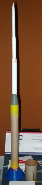
I choose to keep the paint and colors of the Outlander body and plastic parts on the front of the rocket. I masked the nosecone and primed the rest of the rocket with Kilz.
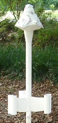
I then sanded with 320 grit to knock off any rough edges. I then cleaned off the dust and painted this with Rustoleum brand Metallic Silver paint. The shine will probably fade quickly but it gives it a nice Fantasy Sci-Fi look. It makes the rocket like a 1960's or 70's Magazine cover.

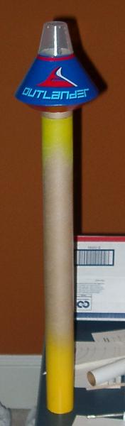
I thought about decals and had a few from a Fliskits rocket that might have looked OK. But nothing I had seemed better than leaving it with just the Outlander decal in place and the rest plain.
Flight:
As with most LPR rockets of this type preparation was fairly simple. First I placed 5 sheets of Estes fire-resistant sheets into the main 24mm tube. After this I folded up the shock cord and pushed it in with my finger. The D12-3 Engine was placed into the rear of the rocket and held in place with an engine hook.
The parachute was dusted with baby powder liberally and then folded carefully with the shroud lines inside. Folding was a bit more complicated than normal - it isn't easy to fold a 24 inch parachute so that it fits loosely in a 24mm tube. The parachute did have a 12 inch spill hole cut into it so it wasn't quite as bad as it sounds - but it took several tries before I was happy with the way it slid in and out of the tube.
Once the parachute was in the rocket I put the nose on. This required turning the nose to match up index marks that I placed on the two. The nose has an internal tube style rod guide which has to be aligned with the lug that I placed on one of the fins. After checking this alignment I put the rocket on a 3/16th inch rod on an Estes Port-a-Pad.
Now I'm not a BAR - I didn't have any rocket experience until about 2 years ago. I'm used to flying off the club pads not off my Estes pad. But since I was trying to squeeze a flight in over lunch - the Estes pad was my only real option. Unfortunately my blast shield was missing, so I improvised and used a disposable aluminum roasting pan - more on this later.
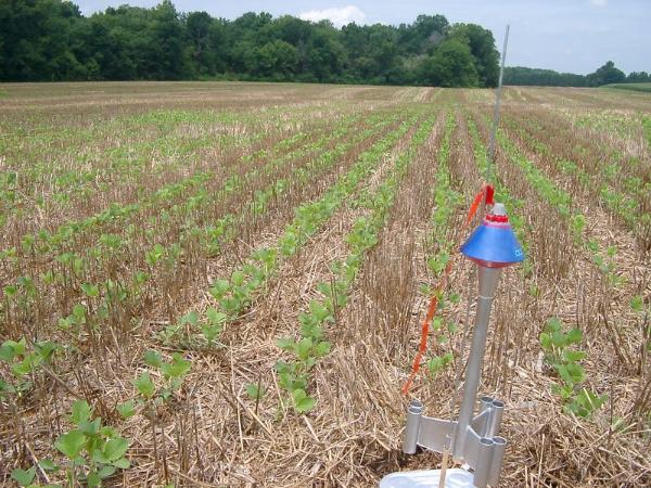
I was unable to find anyone to help with the flight so I had to launch the rocket and take pictures of it at the same time. To make things easier with my slow digital camera I used it in the movie mode. When I pushed the button the rocket took off rapidly and flew straight up. I couldn't tell if the rocket spun or not due to the speed of the flight. I followed the smoke trail up and saw the ejection was a bit too early. Simulations had predicted this but I was worried that the simulations might be too optimistic about the drag. Even with the early ejection the doughnut shaped parachute opened fully.
Right after the parachute opened the rocket drifted in front of the sun and I lost track of it. I quickly grabbed my sunglasses and put them on and looked back - only to find that I couldn't find it. Suddenly I saw it out of the corner of my eye dropping to the ground no more than 50' from the pad. Apparently the rocket had been over my head the entire time! The rocket was stretched out perfectly and appeared completely unharmed.
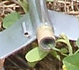
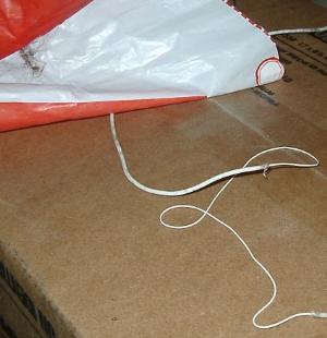
First impressions can be deceiving. As I looked closer I saw that the motor was hanging halfway out of the rocket - the engine hook hadn't retained the engine completely (right). With nothing else looking amiss I picked up the rocket and intended to fly it again. As I began to prepare to pack the shock cord into the rocket - I realized that the cord was nearly broken in two. The shock cord was the cotton covered elastic that I hate but it was what I had in my box. It appeared that somehow the sheath material had been scorched enough to separate. Luckily the elastic under the cover had not been damaged and so the rocket was saved.
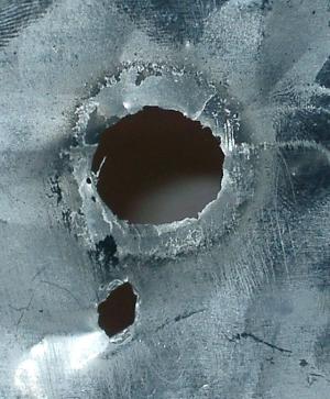
Nothing else was damaged - the rocket was in perfect shape except for the shock cord. The pad however was not so lucky. The roasting pad didn't make a good blast shield - there was a perfectly round hole in the surface - just as if someone had turned a plasma torch on it. (above right) My inexperience using improvised blast shields luckily didn't result in a fire - I had cleared the ground under the pad down to the ground and the constant rain had everything well soaked.
All in all everything turned out very well for a first flight of an unusual rocket. The rocket didn't fly as high as I had hoped so I plan to fly it with a larger motor perhaps an Aerotech E15 or E30. I also plan to swap the shock cord out and perhaps swap the 24 inch parachute for a pair of 12 inch parachutes - one for the nose and one for the body. For anyone planning to clone this rocket I suggest that you stick with RockSIM's estimated delays as a good first guess but expect the altitude to be lower.
Summary:
PRO:
- Spin, Fin, and Tube Stabilization in a single design.
- Electronics bay in front with easy access.
CON:
- Complex to RockSIM - Still not sure it is "right".
- "Requires" epoxy and microballons.
- Drag from the nose makes a larger engine a requirement.
Other:
If I had to do this over I would spend more time during the build documenting the process and writing and rewriting the instructions. This gave me a new appreciation for kit makers.
 |
 |