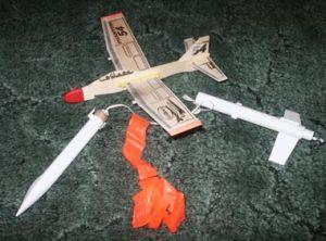
Scratch Phantom Rocket Plane Original Design / Scratch Built
Scratch - Phantom Rocket Plane {Scratch}
Contributed by Owen Kelly
| Manufacturer: | Scratch |
Brief:
Single stage boost glider that uses a modified Guillow's Folding Wing balsa
glider.
Construction:
The following parts list is for the 13mm powered version:
- 1 Guillow's Folding Wing balsa glider
- 1 2.5" BT-5 tube (engine mount)
- 2 BT-5 to BT-20 centering rings
- 1 engine hook
- 1 13mm engine block
- 1 6" long BT-20 tube
- 1 4" long BT-20 tube
- 1 BT-20 nose cone
- 1 BT-20 tube coupler
- 4 3/4" launch lugs
- 3 toothpicks or 1/8" dowel stock
- 1/16" balsa stock for fins and standoffs
- Several pinches of clay for nose weight
- Standard Estes thin shock cord
- 18" streamer
- Glue, pencil, hobby knife, ruler, scotch tape, sandpaper, etc.
- (Optional) One nosecone "socket" with loop for attaching shock cord to BT-20 tube coupler and top half of booster.
- (Suggested) Crystal Clear Scotch Tape, 3M MicroPore tape (first aid fabric tape) or masking tape, used to strengthen the leading edges of all wing and tail surfaces. Estes Tube Marking Guide or VCP software to make fin marking guides.
I would rate this build as easy to intermediate. These instructions expect some basic knowledge of rocketry, like how to mark tubes, cut tubes, assemble engine mounts, etc. The toughest part is getting everything lined up right so the glider separates easily from the booster, yet is held securely during boost. This step should not be too difficult if you follow these instructions.
Booster Assembly
- The best way to start building the booster is to glue the BT-20 tube coupler into one end of the 4" long BT-20. This will be the upper half of the completed booster. If you've got the nosecone socket, you can glue this in place as well, but be sure to use glue compatible with plastic such as epoxy, polyurethane glue, or plastic cement. Once the glue has dried, insert this tube into the remaining 6" piece of BT-20.
- Sand down your body tubes with some medium grit sandpaper. This will allow glue to adhere better to the tubes.
- The next step is to mark the tubes for fins and standoffs/glider mounts. I used the Estes tube marking guides to do this. That makes it really easy to do. If you don't have the marking guides, you can download the VCP program and create marking guides. You will need one marking guide for 3 fins and one marking guide for 4 fins.
- Mark the lower body tube for three equally spaced fins. Run the lines the whole length of the tube. Two of these lines will be used to align fins and the remaining line will be used to align the lower glider mount. I prefer to mark two of the lines with a "F" for fins and the remaining one with a "M" for mount to distinguish them later.
- Mark the upper body tube and the upper portion of the lower body tube for the upper glider mounts and wing supports. Use your four fin marking guide to mark the tubes with two parallel lines, one on either side of the body tube. The easiest way to do this is to align your marking guide with the "M" line you made in the last step and mark lines on either side of that line using the marking guide. Extend these lines from halfway up the lower body tube to the end of the upper body tube.
- Next assemble the engine mount using the adapter rings, BT-5, engine hook, and 13mm engine block. Glue the completed assembly into the lower 6" section of the body tube. Line the lower end of the mount up with the body tube. Give the engine mount some time to dry.
- Now you can glue on your fins. You may use any fin design you desire. Just don't make them very large. I used fins that measure 1.5" along the leading edge and 1" along the root edge. Fin shape should not matter much but you may want to round off the leading edge with sandpaper. Glue your fins to the lines you marked with an "F." Fillet the fins once the root edge joint has dried.
- Create the standoff blocks for the glider mounts and wing supports. Make these by cutting ten pieces of 1/16" balsa that measure 3/16" x 1/4". Glue these together sandwich-style in pairs. When you're done, you should have 5 small balsa blocks.
- Cut three 3/4" lengths of toothpick or 1/8" dowel stock. These pieces will slide into launch lugs and hold the glider onto the booster. Glue the three toothpicks/dowels to the tops of three of the small balsa blocks with one end of the dowel aligned with one end of the block.
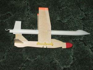
- Once your glider mounts have dried, you can attach them to your booster. The top section of the booster will have two glider mounts attached to it. Glue these pieces even with the end of the upper BT-20 where the tube coupler has been glued in. The dowel rods should extend out past the end of the BT-20 coupler
- Glue the lower glider mount to the lower section of the body tube along the line you marked with a "M." This mount should be lined up with the aft end of the body tube with the dowel extending upward.
- Now you need to glue on the wing supports. These are glued onto the lower half of the body tube along the two parallel lines you extended from the top half of the body tube. The wing supports are glued 3.5" from the bottom end of the lower body tube.
- One thing you may want to do to strengthen your glider mounts and wing supports is to saturate them with CA. This makes the glider mounts a lot stronger and less likely to break off on landing. My upper glider mounts broke off while I was swing testing, so I made the repair with CA at that point.
- Attach your launch lug. This can be wherever you want but just make sure it doesn't interfere with any of the glider mounts.
- Attach the shock cord to the inside of the lower section of the booster with a standard tri-fold shock cord mount. Either tie the other end to the nosecone socket or glue into the BT-20 tube coupler on the top half of the booster. Attach your streamer to the middle of the shock cord with tape.
- The final step in assembling the booster is to securely insert the nosecone into the top end of the booster. You may need to wrap some scotch tape around the nosecone shoulder. Do not glue the nosecone into the body tube. You may need to add clay weight to it later (see CG Placement section below.) Just make sure it is a tight friction fit.
Glider Modifications
- Reverse the clips used to hold the wings onto the body. The glider instructions say to place the open clip at the front of the glider and the closed clip at the rear. I reversed this so that the open clip is at the rear and the closed clip is at the front. The wings are more securely held in place during flight with this arrangement.
- Glue the cockpit piece, the rudder, and the horizontal tail section to the body of the glider with yellow glue. I also coated the rudder and cockpit with yellow glue to add strength.
- I marked the wings and glued on the launch lugs that hold the glider to the mounts on the booster. The launch lugs are glued to the undersides of the wings and are spaced 3 5/8" from the tips of the glider's wings. I glued the launch lugs with 1/8" of the lugs extending past the leading edges of the wings.
- The rear launch lug should be attached to the side of the rudder near the top edge. It should not matter which side (left or right) you attach it to.
- (Optional) I would suggest this as it adds more strength to the glider's vulnerable wing surfaces. It is required if you want to launch the glider with more powerful engines. Coat all wing leading edges with dope, masking tape, MicroPore tape, or scotch tape. Yellow glue may warp the balsa, so proceed with caution if you want to try yellow glue. I used MicroPore tape and it seemed to work fairly well.
- (Optional) I fitted the glider with one rubber band instead of the two that are provided with the glider. The glider's wings are folded outward by the tension of the rubber band. One rubber band creates more tension and causes the wings to unfold more quickly.
Make sure you test fly your glider after making these modifications. You should not need to trim the glider at all because it is already well-trimmed by design. If you do need to trim it, then you can tape some clay to the glider body under the nose or under the horizontal tail section. It should glide quite far when tossed gently.
CG Placement
You should now assemble the glider/booster combo as it would be assembled during flight. Place a few sheets of wadding into the booster, pack the streamer and shock cord in, mount the glider to the booster using the glider mounts, and insert a new A10-3T engine into the engine mount. Balance the rocket booster on a ruler to find the CG. If the CG is behind the trailing edge of the glider's wings, you need to add a pinch or two of clay to the nosecone. The CG should actually be exactly between the wings of the glider. You can check this by tying some string to the booster tube with a slip knot and slide forward and backward to find the CG. You might want to swing test the glider-booster assembly to ensure stable flight. Press clay into end of nosecone with a dowel as necessary.
Flight and Recovery:
Both flights were on A10-3T's at the Southern Arizona Rocketry Association's
May 2005 launch. Thanks to other club members for the comments. The flights
were maybe an 8 on a scale of 1 to 10. Wadding is required. The booster should
be prepped in the same manner as you'd prep any other streamer recovery rocket.
Mount the glider to the booster body once you've put the wadding in and
inserted most of the shock cord into the body tube.
The first launch was just about perfect. The booster fired up and launched, tilting slightly to one side. The flight went a bit squirrelly right before burnout. The ejection charge fired, everything separated smoothly, the booster fell to earth, and the glider descended in a really tight circle. Apart from the funky boost, everything was picture perfect! I was impressed.
The second flight was almost a repeat of the first flight. I don't think the boost went as high as the first flight, but it went up and released the glider right on cue. The glider once again circled tightly to the ground. I can't complain about either flight! Way better than I ever expected.
Summary:
This was a great experience for me being my first attempt at boost glider
launching so I really cannot complain. It actually got quite good air time for
not going as high as I had hoped. I am now working on a BT-50 based booster for
the same glider under A engine power. I would say this project is a good
exercise in scratch building, modification, and boost glider launching.
PROs: A neither too easy nor too hard glider modification, and not a bad first boost glider project for the scratch builder.
CONs: It didn't go that high, which could be remedied by building a more powerful booster. Mildly challenging construction.
 |
 |