| Manufacturer: | Scratch |
Note: This is a slightly condensed version of all the information that Alan has produced for his Level 3 project. Visit his site to read the additional information and enjoy additional pictures.
 Objectives
I realize this may not be a requirement for my L3 project but I believe it is
an extremely integral part of any complex project. I am also a PADI certified
ocean dive and there is a saying that I am sure some of you will recognize if
you are a diver also, it's called "plan your dive and dive your
plan". Basically translated to HPR if you plan your rocket and follow your
plans then your project will have a much higher chance of success and
longevity. I know the amount of coin and time spent on these complex projects
can be enormous and with a little planning and fore thought then these items
will not end up being excavated via shovel from your favorite launch site.
Okay enough philosophy, just a few highlights of what I plan to have my rocket accomplish.
1st: Perform as designed and built. If I follow my plans and objectives then this should be a given.
2nd: Be Cost effective. I guess this depends on several factors, income, budget etc. but we as responsible consumers should only do things within our budgets, I have a nice house but I am not Bill Gates and my rocket is not the next generation of Space Shuttles. Of course it is hard to put the word responsible in this objective, luckily I have no wife to justify why I need dual altimeters as opposed to replacing that old vacuum cleaner.
3rd: Don't re-invent the wheel. There is a lot of great and proven products out there to achieve L3. This is not the time to test and try new and unproven products.
4th: Live long and prosper. Proper planning and construction should result in my rocket attending many launches and burning some substantial AP.
Fin Can / Motor Mount
The main design for the fin can / motor mount was to construct the unit as a
whole and then install the fin can into the booster section. This technique has
been used on 2 previous rockets (Tethy's and original Phasar) with excellent
results. However several construction obstacles where encountered during those
previous attempts that were rectified in this project. The 1st was the ability
to adhere the centering rings level on the motor mount. Usually centerings
rings have some slight play which can easily cause the rings to become slightly
cocked while the epoxy sets up. After some research on some other websites I
found no acceptable techniques. A discussion with my fellow rocketeer, Mike
(HugieBear) Hudgeons revealed the ultimate solution. Mike suggested a cut a 2-3
inch section of the top of the motor mount and slot the entire unit to slide
over the existing motor mount tube and use as a support for the centering ring.
Dude, he hit the jackpot for that solution. I cut a small section off the
existing tube and slotted it on the trusty DeWalt chop saw. A note about chop
saw's, I purchased a 10" DeWalt chop saw from Home Depot for the purpose
of cutting body tubes, the only modification I've done is replace the existing
blade with a metal cutoff blade, man you talk about some clean tube cutting!
Anyway the problem was solved. The 6 centering rings where then tacked into
place with some quick set epoxy. Once the fin can is installed into the booster
tube then small holes will be drilled in between each centering ring and West
Systems Epoxy will be injected with syringes to complete the centering ring
fillets. Once the fillets have set-up then the booster will be inverted to
inject the other side of the rings.
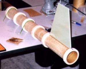 The next construction
problem was the acurate alignment/installation of the 3 fins. The small problem
was actually 3 individual problems, 1st anchoring the motor mount tube
securely, 2nd establish a top dead center point and 3rd enusring the fins are
perfectly vertical. The 1st problem was rectified by drilling 4 holes into my
work desk area and having the ability to use bungee cords to secure the tube to
the work surface. The 2nd problem was to find TDC (top dead center) affordably.
Again a quick trip to the Home Depot to purchase 1 8oz plumb bob, what better
way to find TDC than gravity. Again the plumb bob was attached directly
overhead and centered on the aft centering ring. The 3rd problem was resolved
by tacking the fins to the motor mount with quick set epoxy and using dual
levels to insure the fins where plumb. After the fins where installed a
measurement was made between the 3 fin tips and only a difference of 1/32"
was discoverd between 2 of the fins. I am sure this is more than adequate for
stable flight.
The next construction
problem was the acurate alignment/installation of the 3 fins. The small problem
was actually 3 individual problems, 1st anchoring the motor mount tube
securely, 2nd establish a top dead center point and 3rd enusring the fins are
perfectly vertical. The 1st problem was rectified by drilling 4 holes into my
work desk area and having the ability to use bungee cords to secure the tube to
the work surface. The 2nd problem was to find TDC (top dead center) affordably.
Again a quick trip to the Home Depot to purchase 1 8oz plumb bob, what better
way to find TDC than gravity. Again the plumb bob was attached directly
overhead and centered on the aft centering ring. The 3rd problem was resolved
by tacking the fins to the motor mount with quick set epoxy and using dual
levels to insure the fins where plumb. After the fins where installed a
measurement was made between the 3 fin tips and only a difference of 1/32"
was discoverd between 2 of the fins. I am sure this is more than adequate for
stable flight.
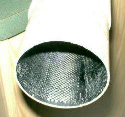
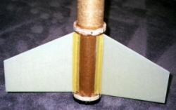 Once the fins where
installed 1" Kevlar®
reinforcement tape was layed in the valleys between the fins and tube with an
8oz layer of fiberglass and Kevlar®
layered over the tube between the fins. As with the centering rings small holes
will be drilled in the booster tube between the fins and injected with West
Systems epoxy for the final fillets.
Once the fins where
installed 1" Kevlar®
reinforcement tape was layed in the valleys between the fins and tube with an
8oz layer of fiberglass and Kevlar®
layered over the tube between the fins. As with the centering rings small holes
will be drilled in the booster tube between the fins and injected with West
Systems epoxy for the final fillets.
After all the reinforcements were installed the 75mm Aeropack was mounted to the aft centering ring with stainless steel screws and nuts.
Airframe Reinforcement
Well now was the time to venture into my 1st attempt with working with Kevlar®.
I heard all the somewhat horror stories and unfortunately Ed from Giant Leap
just introduced his Kevlar®
"socks" about 2 weeks after I placed my order with FibreGlast. Oh
Well! So I will try to pass on any valuable information I gained during this
foray. The primary thing I quickly learned with Kevlar®
is, this stuff is TOUGH to cut. Special shears are a MUST! After discovering
this after my Kevlar®
arrived sent me on a journey to the local fabric store in hopes of finding the
recommended pair which is the Ginger #8-NS-2. Well the fabric stored carried
the Gingher brand of shears only by custom order. Since I was smart enough to
actually bring my Kevlar®
into the store to "test" some shears a salesperson was quickly
summoned for assistance. This was when I discovered there are not a lot of men
in a fabric store with a bundle of Kevlar®
under their arm. Anyway the salesperson was really interested in the Kevlar®
and responded with the phrase: "isn't that what they make bullet proof
vests from?" now we are having fun. She steered me to another brand of
shears called Fiskars and we tried several different models with little success
then we tried the "RAZOREDGED" model and we where off to the races!
Great shears and only about $18.00.
 Luckily my TAP member
Derek Deville had worked with Kevlar®
before and gave me some great advice about working with it. The basic plan was
to use 2 layers of the 5oz 17x17 5HS Kevlar®
followed by a finish wrap of 2oz fiberglass for finishing purposes. Derek had
recommended using the preferred method allowing the layers to setup until tacky
before applying the next layer as opposed to letting the layers completely
cure. So I set aside the whole day for using this method which actually creates
a chemical bond between the layers as opposed to a mechanical bond by having
layers applied after they have cured. One good thing about these Texas summers
is epoxy cures real fast in a 100 degree garage. Prior to applying the Kevlar®
the booster tube was prepped using 80 grit sandpaper and thoroughly cleaned. I
mixed up some generous portions of the West System and started applying a layer
directly to the tube. Once a tack coat was applied I started layering on the
Kevlar®
being carefull not to stretch the fibers and to work the epoxy into the
Kevlar®.
After the Kevlar®
was completely wrapped I went over the entire tube using a plastic squeegie and
removed any excess resin. The Kevlar®
applied very nicely much like a heavier fibreglass, I had almost no buckling at
all and actually enjoyed working with it. After this 1st layer was applied I
set back and waited for the resin to start curing in preperation for the 2nd
layer. Continued checking the "tackiness" until about 2 hours had
passed and determined the tube was ready for lasyer 2. The next layer was
applied in the exact same manor as layer 1 with the same great results. In
conclusion I have to say many of the stories I heard about using Kevlar®
were a little exagerated. Yes it does take a little extra work and some special
shears but I really loved the way it wet-up and applied.
Luckily my TAP member
Derek Deville had worked with Kevlar®
before and gave me some great advice about working with it. The basic plan was
to use 2 layers of the 5oz 17x17 5HS Kevlar®
followed by a finish wrap of 2oz fiberglass for finishing purposes. Derek had
recommended using the preferred method allowing the layers to setup until tacky
before applying the next layer as opposed to letting the layers completely
cure. So I set aside the whole day for using this method which actually creates
a chemical bond between the layers as opposed to a mechanical bond by having
layers applied after they have cured. One good thing about these Texas summers
is epoxy cures real fast in a 100 degree garage. Prior to applying the Kevlar®
the booster tube was prepped using 80 grit sandpaper and thoroughly cleaned. I
mixed up some generous portions of the West System and started applying a layer
directly to the tube. Once a tack coat was applied I started layering on the
Kevlar®
being carefull not to stretch the fibers and to work the epoxy into the
Kevlar®.
After the Kevlar®
was completely wrapped I went over the entire tube using a plastic squeegie and
removed any excess resin. The Kevlar®
applied very nicely much like a heavier fibreglass, I had almost no buckling at
all and actually enjoyed working with it. After this 1st layer was applied I
set back and waited for the resin to start curing in preperation for the 2nd
layer. Continued checking the "tackiness" until about 2 hours had
passed and determined the tube was ready for lasyer 2. The next layer was
applied in the exact same manor as layer 1 with the same great results. In
conclusion I have to say many of the stories I heard about using Kevlar®
were a little exagerated. Yes it does take a little extra work and some special
shears but I really loved the way it wet-up and applied.
 Once the 2nd layer of
Kevlar®
started setting-up the finish coat of 5oz fiberglass was applied. Again no
surprises here it applied perfectly to the existing Kevlar®
with excellent results when completely cured. This tube feels indestructible!
Once the 2nd layer of
Kevlar®
started setting-up the finish coat of 5oz fiberglass was applied. Again no
surprises here it applied perfectly to the existing Kevlar®
with excellent results when completely cured. This tube feels indestructible!
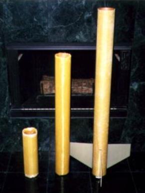
On July 9 after the McGregor launch I prepped the upper airframe and booster extension section (12" since I can not fit all the required recovery in a standard 4' booster section) for the Kevlar® laminates. This will give the booster section an overall length of 60". The upper airframe section is 36". Basically no suprises here during the Kevlar® and fiberglass lay-ups with the same great results as the booster section.
Fin Can Installation
Prior to installing the fin can the booster section had to reslotted due to the
reinforcements. I was a little concerned about not being able to see the
existing slots after applying the
 Kevlar®
but realized they showed up fairly well through the multiple layers of Kevlar®.
The slots were recreated using the trusty table saw and this time they were
slotted all the way to the back of the tube to allow for installing the fin
can.
Kevlar®
but realized they showed up fairly well through the multiple layers of Kevlar®.
The slots were recreated using the trusty table saw and this time they were
slotted all the way to the back of the tube to allow for installing the fin
can.
Now it was time install the fin can and start injecting West Systems to create the reinforcing fillets for all the centering rings and fin joints. Prior to installing the fin can carefull measurements where done to show where each of the centering rings would be in the booster section. This would facilitate where to drill the holes to inject the West Systems. Marks where made on the outside and drilled with a 1/4" hole. These holes will later be filled in with a small piece of Kevlar®. Next step was to create a very smooth fit for the fin can into the booster section. Some quick sanding was required to achieve that perfect slide into the booster.
Recovery Attachment Modules
I usually construct my recovery attachment modules as seperate components then
epoxy the units in place in the body tubes and with this project the procedure
would basically be the same.
The materials used to construct the booster section and forward airframe attachment modules are:
- 4 ea. 3.5" length of coupler tubing
- 2 ea. 1/2" x 6 ply coupler bulkhead plate
- 2 ea. 1/2" x 6 ply airframe bulkhead plate
- 2 ea. 3/8" x 5" Eyebolt
- 8 ea. 3/8" Nuts
- 8 ea. 3/8" Fender washers
 Building these
components as unit then installing into the airframe is much easier than
installing each component into the airframe.
Building these
components as unit then installing into the airframe is much easier than
installing each component into the airframe.
After the bulkhead units were installed into the couplers small holes were drilled in the center of the couplers to allow for injecting the West Systems epoxy and creating the bulkhead fillets on both sides. The units are extremely strong and allow for a large area of distributing the shock load during deployment. One special note is the use of the regular eyebolts as opposed to either forged or welded. While these definitely offer some added margin of error it would still take over 400lbs. to even begin to straighten out the eyes. I believe if my deployment induces that much force to fail my eyebolts then the are some other serious problems going on that no eyebolt will solve. The extra section of coupler will be epoxied in place on top of the exposed bulkhead plates. A sufficient amount of West Systems will be poured on top of the exposed bulkhead while it is in the airframe and then the coupler section will be fitted into place to allow for extra reinforment not only to the attachment module but to the airframe tubing as well.
 Nosecone
My goal here was mostly add some weight to the front of the PHASAR and add an
attachment point of some kind just in case I use it on another future project.
This was pretty straight forward for me, since the nosecone is a ScotGlas all I
had to do was mix some West System up, pour into the nosecone and let cure. I
estimate I added approximately 10oz. using this process. Next was to firm up
the shoulder with some 1/2" Birch bulkhead plates and add an eyebolt in
case I ever need to attach a recovery system to it. Again the design was just
like the components in the recovery attachment modules with a 3/8" x
5" eyebolt running through both bulkheads which were spaced about 2"
apart. Next all I had to do was sand the unit some to fit the slightly
irregular shape on the inside of the shoulder and position inside the nosecone
shoulder for epoxying. Also for improved fillets on the bulkheads I drilled 2
small holes between the plates for easy injection of West Systems and some
really beefy fillets. After all was said and done I measured the distance from
the nosecone rear bulkhead to the shoulder rest point and transferred this
measurement to the forward airframe section of the PHASAR. I then drilled 3
3/16" holes through the airframe into the 1/2" bulkhead plates. Then
I used 3 of the same inserts used by the BlackSky Aluminum Rail Guide buttons
and attached the nosecone with 8/32 stainless steel machine screws.
 Coupler
Reinforcement
Coupler
Reinforcement
Since I was using standard phenolic couples I wanted to reinforce the inside
area to withstand any zippering effect during deployment. I researched this
area of reinformcent from several other individual websites and the best idea
came from the Gate's Brother Website illustrating lining the inside of the
coupler with Kevlar®
then Carbon Fiber while inflating a balloon inside the couple to expand the
materials and compress the West Systems epoxy and cloth. The 1st layer was the
Kevlar®
followed by a finish layer of 5.7oz carbon. This method produced a glass smooth
interior lining plus added extreme strength to prevent a shock cord from
zippering during deployment.
Electronics:
The PHASAR will incorporate dual Olsen FCP-M2 altimeters. I have used the Olsen
FCP-M2 in my previous Phasar project and have had nothing but excellent
performance with this unit. The ease of use, programmability and data downloads
made this choice a no-brainer. The FCP-M2's have a nice feature that allows for
a delay at apogee detection for the backup unit so both charges will not fire
simutaneoulsy. The main unit will have a charge set for 750' and the backup
unit set for 650'. Another good reason for using the FCP-M2 is there ability to
set main chute deployments in 50' increments as opposed to 4 or 6 main chute
settings.
The design of unit is from my good friend Steve Baughman, a completely modular unit which can be incorporated in any of my 4" rockets.
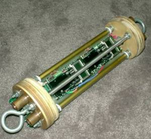 The construction of
the unit was fairly straight forward with the exception of the Olsen's being
mounted in a modular way to allow for easy access. So after my 1st design I
wanted to incorporate a "inner frame" which would hold the Olsen's.
The primary problem with the design was the limited space in a 4" tube for
dual electronics plus all the associated wiring involed to remain modular and
accessabile. The result was the inner cage which would hold the Olsen's.
The construction of
the unit was fairly straight forward with the exception of the Olsen's being
mounted in a modular way to allow for easy access. So after my 1st design I
wanted to incorporate a "inner frame" which would hold the Olsen's.
The primary problem with the design was the limited space in a 4" tube for
dual electronics plus all the associated wiring involed to remain modular and
accessabile. The result was the inner cage which would hold the Olsen's.
The next part was to design the board unit on which the Olsen's would mount and slide over the all-thread rods. This was accomplished with a piece of .125" G10 cut to width and height to fit in the avioncis section. Now, how to attach the unit to the all-thread rods running through the avionics section and still be removable. Another good friend of mine Mike Hudgeons came up with the design of using aluminum arrow shafts as the guides to slide over the all-thread rods. This unit will now slide over the all-thread rods and allow for easy removal. Carefull planning and a template allowed for drilling the holes in a pattern that would allow for all the components. * Mounted G10 on Arrow shafts
Now the next part was to mount the Olsen's on the G10, no problem here just used the hole template sent with the units with some standard nylon stand-offs. The other item I corporated was drilling holes in the G10 for the wiring to pass through plus the addition of nylon tie straps for battery retention.
 The next problem to
overcome was managing the wiring and making that portion modular. The solution
was using computer part wiring harnesses, the wire guage was perfect and the
connectors would allow for easy removal without having to undue the actual
connections to the screw termimals on the Olsen's. The wiring harness is held
in place on the G10 with plastic wire holders.
The next problem to
overcome was managing the wiring and making that portion modular. The solution
was using computer part wiring harnesses, the wire guage was perfect and the
connectors would allow for easy removal without having to undue the actual
connections to the screw termimals on the Olsen's. The wiring harness is held
in place on the G10 with plastic wire holders.
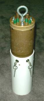
The next consideration was how to external arm the units at the launch pad. Again, another great friend of my, Ed Jacoby turned me on to key switches, the only problem with the previous units where the length would not allow for the unit to slide into the bay area. The solution was solved from Hawk Mountain which sells some great key switches that are fairly short and would allow for the unit to slide into the bay area.
All in all the desgin and construction required some careful fore-thought and a lot of inspiration from my fellow rocketeer's that culminated into a great desgin that I feel very confident in achieving my L3 status.
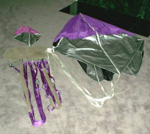
Recovery
The PHASAR will use 2 SkyAngle Cert-3 chutes.
I consider the recovery devices and design the 2nd most critical components of the project with the avionics being 1st. "Getting it up is the easy part, getting it back takes some skill." With that in mind I did NOT cut any corners when designing the recovery system and components. First off is to start with quality and proven components. My choice was SkyAngle Level 3 Cert Chutes. I have used their products in my past projects and swear by their quality. A previous rocket, the Binder Cobra suffered a premature separation during boost on a J-415W and the SkyAngle regular 60" chute held up and brought my rocket safely back to earth with no damage! What a testimony to their product.
 The overall design
and configuration of the dual deployed recovery systems is having the avionics
section situated between the forward payload and rear booster sections. When
the PHASAR reaches apogee the avionics bay will seperate from the booster and
deploy the drogue chute. Once the PHASAR enters the pre-selected main
deployment altitude then the forward payload section will seperate from the
avionics section and deploy the main.
The overall design
and configuration of the dual deployed recovery systems is having the avionics
section situated between the forward payload and rear booster sections. When
the PHASAR reaches apogee the avionics bay will seperate from the booster and
deploy the drogue chute. Once the PHASAR enters the pre-selected main
deployment altitude then the forward payload section will seperate from the
avionics section and deploy the main.
The 2 chutes to be used in this project are the SkyAngle Cert-3 drogue chute and a SkyAngle Cert-3 15-25lb. main chute.
The other recovery components used in the system is 9/16" tubular nylon rated at 2000 lbs., 3/8" Quick Links rated at 1200 lbs., Giant Leap 1500 lb. swivels to prevent line wrap, Nomex cord protectors and Nomex chute protectors.
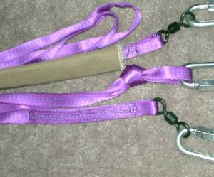 Each section of the
tubular nylon is 25' which gives an overall length of the PHASAR when fully
deployed at 61.5' Believe me it barely fits in the backyard when fully
deployed!
Each section of the
tubular nylon is 25' which gives an overall length of the PHASAR when fully
deployed at 61.5' Believe me it barely fits in the backyard when fully
deployed!
Each end of the tubular nylon was professional sewn with the Giant Leap swivels with an overlap of 6".
I can't emphasize enough here how important it is to use quality products when implementing your recovery system. I consider the best advice comes from my fellow rocketeer's about what works, what doesn't and the pro's and con's of each item. Take time to investigate these items.
RockSim 5.0
Since I started updating this website Apogee Components came out with the new
RockSim 5.0 and I was quick to respond to this upgrade.
The new version is a must for any serious rocketeer looking to develop a high performance vehicle.
I can't emphasize enough the importance of great design/simulation software and RockSim 5.0 is the tool to use. I won't go into all the new features as I have not even discovered them all myself yet, but suffice to say this is the premiere software for some serious projects. Here are some of the screen captures from the new version of the PHASAR.
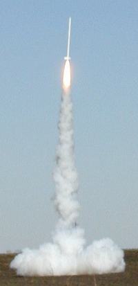 SUCCESSFUL LEVEL 3 FLIGHT!
October 27, 2001
Dallas/Fort Worth, TX.
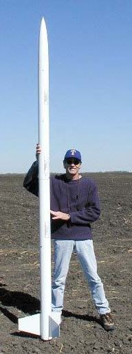
Rocket - Scratch Phasar
Weight - 36 lbs
Motor - Aerotech M1315
Altitude 11,621 feet
Flight:
The event was the much cancelled North Texas High Power/Shoot for the Stars
event here north of the DFW area, this is our premiere site in Texas with over
1600 acres of cleared farm land and waivers to 23,500' MSL. The event took
place this past weekend on October 27-28. Of course my Phasar project has been
ready since September of 2000, so not much to do, the M1315W was loaded last
year in anticipation, I keeped the closures just barely on not to deform the
o-rings and re-greased everything prior to departing to the launch site Friday
evening. I think the only modifications I did to the original design were some
wiring harness modifications to make it full-proof to mis-wire any of the
altimeters/ejection charges and external key switches, plus I switched my
regular eyebolts to the 3/8" forged shoulder units and the addition of
shear pins at both separation points. (Ground tested of course) Kind of
interesting what a year of sitting around looking at your project and what can
you do to improve your chances of success will do. Anyway I was now giving
myself about a 90% chance of success since the modifications. Extremely
confident in my abilities and design but you can never foresee that inevitable
bad luck that sometimes happens in a project of this magnitude.
 Anyway
the weather forecast for the weekend were outstanding, clear blue skies, in the
low 70's with winds 5-10mph! Finally the rocket gods were shining down on me!
We arrived at the site Saturday morning, I had a crew of 2 (Glenn Carey from
Brownwood, Texas and Mike Martin from Missouri City, Texas) Level 2 guys plus
my local TAP member Tom Montemayor give the Phasar one last inspection and was
given the thumb's up from all of them. The Phasar was pretty much completely
prepped prior to departure to the site, recovery systems, electronics, ejection
charges, etc. The only field prep was to attach the shock cords to the av's bay
and install the shear pins, a grand total of 5 minutes and then off the away
cell. I know this is where other L3 projects check off an extensive list of
things to do, check , etc. but I felt I do this with every L2 flight and the
only difference here was the motor size. I guess that's what 40 L2 flights does
for you, create an established procedure to fly and recover your rocket, no
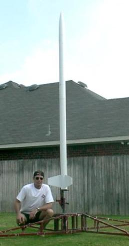
difference here for me at least! Anyway we lowered the rail, slide the Phasar
in position, armed the electronics, stood the Phasar up, carefully I might add
since I could not reach the arming switches when in the vertical position,
installed the igniter, check continuity, and have some photos op's! I was at
the away cell less than 10-minutes much to the amazement of the crowd, that's
what practice/experience does for you! I've seen other people do there L3 and
at the pad for an hour or so, now that would make me nervous!, what the hell
are they doing? Anyway back to the RSO with my thumb's up. The waiver was in
place for an estimated altitude of 11,300'. Skies where checked for aircraft,
since we are in the flight path of DFW, and the countdown was announced, at
t-minus 0 with Shelly Hatten at the RSO duties the LCO pressed the button and
the 1st presence of the igniter beginning to pressurize the M1315W was visible,
then the M1315W quickly came up to full pressure and the Phasar began it's
vertical ascent to the heavens. There was a very slight pendulum motion since
the static margin of stability was about 9.5 for a 4" rocket but once the
Phasar gained speed it was nothing less than an arrow straight boost skyward.
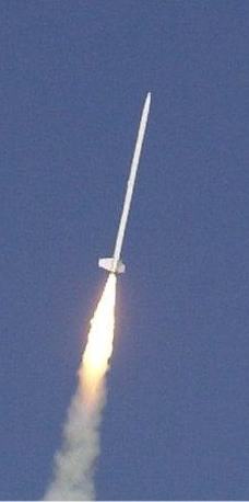
Also noted was the slight kick into the prevailing winds since the fin area was
quite large. These 2 events were very predictable based upon my design and was
actually a far more straighter flight than I originally predicted. Anyway the
Phasar continued it's fantastic vertical ascension to apogee under the thrust
of the 5.3 second burn time of the M1315W, a beautiful arc over and the
tell-tale sign of smoke of an ejection charge going off separated the booster
from the forward section and deployed the cert-3 skyangle drogue and began it's
rapid descent back to earth. Then right on queue the main charges blew at 1200'
and deployed the cert-3 large skyangle chute for it's finally journey back to
the confines of gravity. It landed about 1.5 miles away and recovery was fairly
simple, it landed in a wide open freshly plowed field, what a soft landing!
Anyway
the weather forecast for the weekend were outstanding, clear blue skies, in the
low 70's with winds 5-10mph! Finally the rocket gods were shining down on me!
We arrived at the site Saturday morning, I had a crew of 2 (Glenn Carey from
Brownwood, Texas and Mike Martin from Missouri City, Texas) Level 2 guys plus
my local TAP member Tom Montemayor give the Phasar one last inspection and was
given the thumb's up from all of them. The Phasar was pretty much completely
prepped prior to departure to the site, recovery systems, electronics, ejection
charges, etc. The only field prep was to attach the shock cords to the av's bay
and install the shear pins, a grand total of 5 minutes and then off the away
cell. I know this is where other L3 projects check off an extensive list of
things to do, check , etc. but I felt I do this with every L2 flight and the
only difference here was the motor size. I guess that's what 40 L2 flights does
for you, create an established procedure to fly and recover your rocket, no
difference here for me at least! Anyway we lowered the rail, slide the Phasar
in position, armed the electronics, stood the Phasar up, carefully I might add
since I could not reach the arming switches when in the vertical position,
installed the igniter, check continuity, and have some photos op's! I was at
the away cell less than 10-minutes much to the amazement of the crowd, that's
what practice/experience does for you! I've seen other people do there L3 and
at the pad for an hour or so, now that would make me nervous!, what the hell
are they doing? Anyway back to the RSO with my thumb's up. The waiver was in
place for an estimated altitude of 11,300'. Skies where checked for aircraft,
since we are in the flight path of DFW, and the countdown was announced, at
t-minus 0 with Shelly Hatten at the RSO duties the LCO pressed the button and
the 1st presence of the igniter beginning to pressurize the M1315W was visible,
then the M1315W quickly came up to full pressure and the Phasar began it's
vertical ascent to the heavens. There was a very slight pendulum motion since
the static margin of stability was about 9.5 for a 4" rocket but once the
Phasar gained speed it was nothing less than an arrow straight boost skyward.
Also noted was the slight kick into the prevailing winds since the fin area was
quite large. These 2 events were very predictable based upon my design and was
actually a far more straighter flight than I originally predicted. Anyway the
Phasar continued it's fantastic vertical ascension to apogee under the thrust
of the 5.3 second burn time of the M1315W, a beautiful arc over and the
tell-tale sign of smoke of an ejection charge going off separated the booster
from the forward section and deployed the cert-3 skyangle drogue and began it's
rapid descent back to earth. Then right on queue the main charges blew at 1200'
and deployed the cert-3 large skyangle chute for it's finally journey back to
the confines of gravity. It landed about 1.5 miles away and recovery was fairly
simple, it landed in a wide open freshly plowed field, what a soft landing!
After the recovery the 2 Olsen's where downloaded and the final altitude was 11,621'! with a max acceleration of 325 ft/sec. The figures were about 350' off of what RockSim 5.0 predicted and the altitude difference between the 2 identical Olsen's was 208'.
In conclusion, I have to think the entire project and attempt meet and exceeded all my goals of design and performance and reinforced my believe that I DO know what I am doing!
 Post-Flight
Objectives Analysis
Post-Flight
Objectives Analysis
1st: Perform as designed and built. The Phasar L3 performed almost exactly as I intended it to based upon all my RockSim calcualtions and design. I knew the rocket was overstable with a static margin of stability of 9.5, which is not bad, but anticipated a slight pendulum motion off the pad until the M1315W gained enough velocity. After review of the flight video this is exactly what happened, a very slight back and forth motion in the booster section for about 1 second of the flight. Also anticipated a slight weather cock depending on the wind speeds at launch time since the fin area was quite large for a 4" diameter rocket. The winds during the launch were about 7mph and the rocket was launched perfectly perpendicular to allow for a slight weather kick. Again the flight video revealed the rocket did a slight kick right into the prevailing winds that day. These 2 items were anticipated and the Phasar L3 performed exactly as Rocksim would have predicted.
2nd: Be Cost effective. In my opinion I believe the total and final cost of construction and flight ofthe Phasar L3 was quite reasonible for a project of this magnitude.
3rd: Don't re-invent the wheel. There was no products and/or procedures that I used in the development of the Phasar L3 project that had not be used in any of my previous rocket endeavours with the exception of using shear pins for the 1st time. The shear pins were used only after sufficient ground testing and consulation with my TAP members.
4th: Live long and prosper. The Phasar L3 survived an extreme L3 attempt without any damage and there is no reason additional 75mm motors will not be used in this launch vehicle.
In Conclusion:
I developed the Phasar L3 program around these ideas and proven techniques and
followed my objectives as close as possible and believe because of this the
project was a complete success on it's 1st attempt.
 |
 |