Scratch Polaris Original Design / Scratch Built
Scratch - Polaris {Scratch}
Contributed by Jan-Hein Ramakers
| Manufacturer: | Scratch |
Note: This is a slightly condensed version of all the information that Jan-Hein has produced for his Level 3 project. Visit his site to read the additional information and enjoy additional pictures.
 Introduction
After the successful flight last year of my level 1 project I started thinking
of a bigger rocket, not just a little bit bigger but a real huge one. At least
2 meters in length and a minimum diameter off 6". If you like to build a
large rocket you also need a sturdy engine at least more than a I type engine.
So off we went for a level 2 certification. The first flight of the rocket, a
modified North Coast Archer wasn't a big success due to a failure of the
ejection charge, the rocket smashed into the Swiss clay causing the PML nose
cone to melt on impact. As far as I could see the rocket performed (except for
the recovery) ok, so I decided to build a new one. This time there was an Rdas
computer onboard which took care of the two stage recovery. And on the second
attempt, everything worked the way it was meant to be and I received my level
two certification.
Now there was nothing going to prevent me from building a real big fat rocket.
After looking around on the internet for a proper design to build as a level III project and going through several old HPR magazines I finally found a rocket that I liked. It was on my own home page :-). First I intended to build a scale model of a Nasa test rocket the NASA Motor Test Vehicle, but while making the drawings for the rocket I found that it was going to be a hell of a job. At first the rocket looks very simple but I had to make a special nose cone (I also made the cone for Berts level 3 Orion) and it would be a lot of work to make another one. Besides that, the rocket has a pair of profiled fins that didn't look like it was possible to make them from a single piece of G10 or plywood.
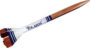
Considering all this, I decided to look for another design and there it was; the Polaris. Standing right in front of me on my desktop; straight tube, flat fins, ogive nose cone and just the rocket I was looking for (if you are looking for your glasses you probably are sitting on them). The design would be simple; four fins made of 3 layers laminated plywood, a body tube of 200mm reinforced cardboard tube, and the same nose cone I made for Berts level 3 project.
 Concept
I was going to use a building concept used form any years in real rocketry; the
laminated foam cored sandwich. It would be a very simple design with no
difficult shapes and as much as possible following the KISS concept recovery
system with redundancy built in, and anti-zipper airframe. The rocket must be
strong, but as light as possible. The Polaris is going to have the opportunity
to fly on a cluster. A central 75mm and four 38 mm cluster engines with an air
start option.
The rocket must have a static margin of at least 1.5. The rocket recovery system will not break the rocket apart in two places, but will blow of the nose cone with the upper part of the body tube (no need for sheer pins). The rocket must be very simple to prep and if possible, pre-prep the complete rocket (except for the engines).
The rocket will have a sandwiched construction made of an outer tube of phenolic impregnated cardboard (flexible phenolic) covered with glass fiber with an inner section of 2-component foam and a regular Phenolic tube. This way of constructing has several advantages; no couplers to make an very strong and durable construction zipper free, lightweight and super strong in all directions.
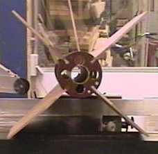
The fins will be made from three layers of airplane ply; an inner section of 8mm with a layer of 3mm on each side. In the 8mm center core several holes will be cut to lose some weight on the lower section of the rocket. The booster part of the rocket will be made of a central 75 mm phenolic tube reinforced with glass fiber and four 38 mm with glass fiber reinforced phenolic tubes for clustering. All hollow parts will be filled with 2 component construction foam.
The electronics will have a special compartment between two of the fins and will be accessible from the outside of the rocket. Triggering will be done by two Safety plugs.
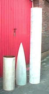
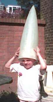 Nose Cone
The nosecone will have a central phenolic tube to add weight and all hollow
parts will be filled with 2 component construction foam.
 Airframe
The airframe will be built by laminating two layers of glass fiber to an
impregnated cardboard tube. The components of the airframe (fin section,
avionics bay and recovery bay will be made of one part. To again create a light
but strong construction.
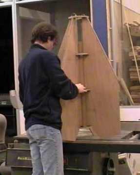
Fin Section
The fins will consist of 10 mm Ply and will be epoxied to the motor mount, the
centering rings will be made of 12 mm high density airplane grade plywood.
Now we are more than 6 months later. And I finally found some time for an update. Not that I did any building in the mean time, (it was just to busy) running a rocket company and having a full time job is consuming more time than expected.
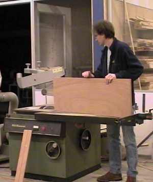
A friend of mine offered me some help, I know I have to build the rocket myself but once in a while the construction is just to big and heavy to handle it alone. Besides that, he has a work shop so the rocket can stand upright on its feet. (Thanks Ton).
While making the drawing we found out that the construction I had in mind wasn't going to fit into the body tube, so the decision was made to change the 54 mm boosters to 38 mm boosters.
Second the electronics bay that was planned between the motor and the recovery section was omitted and brought down to the fins.
Here, just between two of the fins the electronics will do their job. Air start the boosters and take care of the apogee detection.
A Second payload bay will come in the upper section and will consist of two RDAS computers and they will take care of the recovery.
Now it is time to make an appointment with the tap members to see what they think of my construction idea (before I do any real building). Ok, we made the fins, the nose cone, a very big bunch of rings, and two body-tubes with a coupler but didn't use any epoxy yet (I really can't wait).
Changes
The plans have had some minor changes. One of the changes we made was the
position of the payload section. In stead of positioning the electronics in a
bay under the nosecone. I decided to make a bay in the booster section so the
same bay could be used to store the apogee detectors and air start timers along
with two Rdas computers for flight data and recovery.
LEVEL 3 - PENDING FLIGHT
Date
Where
Rocket - Scratch Polaris
Weight -
Motor -
Altitude
The new date for the test flight will be ALRS in Switzerland 2003 (date unknown)
 |
 |