Scratch Quasar (Upscale) Original Design / Scratch Built
Scratch - Quasar (Upscale) {Scratch}
Contributed by Steven Rogers
 Note: For
additional and larger pictures visit Steven's site.
Note: For
additional and larger pictures visit Steven's site.
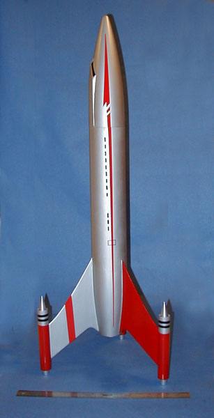
The Quasar was among my favorite rockets in terms of style. Its simple and elegant 50's style is quite appealing. I also like the "jet" look of the pods. The jet cones and tails in the original kit were my first encounter with vaccuform. The original Quasar had an ejection baffle - mine met its end through the shock cord coming out of the main body.
Scaling
After playing with the numbers, I selected two scales as optimal for a scale-up: 2.43x for a 4 inch tube, and 4.6x for a 7.5 inch main body tube. This page is about the 2.43x project - a learning project before taking on the 7.5 inch version. (click on Steven's Home Page icon to find information about this project)
Design
With a clone, the basic shape of the rocket is set so the design involves working out how to make the larger shapes with different parts, tweaking sizes here and there for appearances sake, and making sure the whole thing is still stable. A clone is not guaranteed to be stable - the CP will be in the same place if you replicate the shape but the materials and construction techniques are so different that the CG may move aft significantly as a design is enlarged.
You can take a look at the Rocksim data file to see how all the parts stack up. (see RockSim link above, right of title)
Construction Details
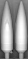
In the original, the tail cone is made from a paper shroud, and is straight. In the scale up, I decided to use a nose cone for this surface to create a curved boat-tail. This is partially because I think the nose cone will make a stronger tail than a styrene sheet, and partially just because I like the look of the curved tail better.
 I happen to have an original Quasar fin sheet. This is
not from my original kit, but from a "grab bag" box I ordered from
Centuri around '75 or '76. I think it cost a few dollars and was a starter kit
box jammed full of pre-printed fin sheets, nose cones, tubes, and decal sheets.
I scanned this and compared it to the image on JimZ's site, and there are
significant differences in the size and the curve at the root trailing edge.
The pattern on Jim's site was traced from the fin on a built rocket - which is
probably the reason it isn't too accurate. It should be updated with this one
soon. Also, the decal on Jim Z's site downloads as 300 DPI, but it is actually
scanned at 600 DPI. This will make your decal 2x too large if you use the image
directly as downloaded.
I happen to have an original Quasar fin sheet. This is
not from my original kit, but from a "grab bag" box I ordered from
Centuri around '75 or '76. I think it cost a few dollars and was a starter kit
box jammed full of pre-printed fin sheets, nose cones, tubes, and decal sheets.
I scanned this and compared it to the image on JimZ's site, and there are
significant differences in the size and the curve at the root trailing edge.
The pattern on Jim's site was traced from the fin on a built rocket - which is
probably the reason it isn't too accurate. It should be updated with this one
soon. Also, the decal on Jim Z's site downloads as 300 DPI, but it is actually
scanned at 600 DPI. This will make your decal 2x too large if you use the image
directly as downloaded.
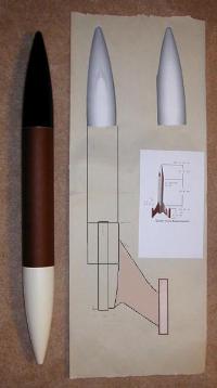
The first step in construction is to make a full size plan. This might seem tedious, but I always start this way, and it helps to work out the design problems and is a nice aid in building. For this particular rocket, the plan helped in adjusting the nose cone, body tube, and tail cone lengths to get the right overall size, as well as making a fin pattern with precise TTW fin tabs. The nose cone was laid out, including the cockpit, by enlarging a photo of an original nose cone to proper size. (I got the photo from someone who was kind enough to email it - lost track of who now).
The precise curve of the boat tail can be transferred to the plan using a square
- Engines: TBD 29mm
 Resources
- The Quasar on JimZ's plans site
- A legacy of Quasars from Sven's Knudson's archive
- Quasar 71
- Quasar 72 (the year of my original catalog)
- Quasar 73 (same as '72)
- Quasar 74-75 (same as '72)
Building the Jets and Nose
 The original
"jet" nozzles in the pods were vaccuform discs with a cone in the
center. The design was probably supposed to capture the look of a jet engine
inlet with the flat fan blades and a cone in the center. Since this rocket is
such a large scale up, I decided to take some liberties with the jet inlets to
improve the appearance. The "cone" is provided by a nose cone, and
there is no disc inside. During flight, the air will be able to flow through -
perhaps it will make some kind of interesting sound that will add to the
flight.
The original
"jet" nozzles in the pods were vaccuform discs with a cone in the
center. The design was probably supposed to capture the look of a jet engine
inlet with the flat fan blades and a cone in the center. Since this rocket is
such a large scale up, I decided to take some liberties with the jet inlets to
improve the appearance. The "cone" is provided by a nose cone, and
there is no disc inside. During flight, the air will be able to flow through -
perhaps it will make some kind of interesting sound that will add to the
flight.
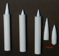
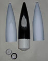
I finally settled on the shorter of the PNC-50 cone because of its resemblance to the typical cone shape inside a jet engine. There is also somewhat of a dilemma as to how far to let it protrude from the tube. About half an inch seems to capture the look fairly well.
 The
cockpit was hand-molded using Aves "Fix-it" from
Apogee Rocketry. It took three applications to get the
cockpit fully laid out properly. I also made it wider and flatter to blend in
with the overall appearance of the larger rocket.
The
cockpit was hand-molded using Aves "Fix-it" from
Apogee Rocketry. It took three applications to get the
cockpit fully laid out properly. I also made it wider and flatter to blend in
with the overall appearance of the larger rocket.
Final Assembly
 The last steps in assembly
are to give the rocket a coat of finishing resin to smooth out the bumps, paint
it, add the jet pod cones and exhaust, and the decals. The jet cones are nose
cones with slots cut in the base so they will lock onto the portion of the fin
tab that extends into the jet pod. Similarly, the jet pod exhausts are just
plastic bottle caps glued onto plywood tabs that fit on the base of the fin
inside the jet pod. They are all set up to the same length, so they all extend
the same distance out the jet pod.
The last steps in assembly
are to give the rocket a coat of finishing resin to smooth out the bumps, paint
it, add the jet pod cones and exhaust, and the decals. The jet cones are nose
cones with slots cut in the base so they will lock onto the portion of the fin
tab that extends into the jet pod. Similarly, the jet pod exhausts are just
plastic bottle caps glued onto plywood tabs that fit on the base of the fin
inside the jet pod. They are all set up to the same length, so they all extend
the same distance out the jet pod.
Giving the tail cone a good coat of finishing epoxy proved important to getting a smooth finish between the body tube and cone. Getting the epoxy to stick required sanding the cone with #60 paper until it is fuzzy enough to create a mechanical bond. Then two coats of finishing resin with sanding in between create a surface ready for primer.
Decal patterns were created mostly from vinyl, with the lettering created by Tango Papa decals.
I went nuts with photoshop and created some space scenes using images of the Quasar along with computed generated "space stuff". You can find these on my site or in the EMRR's Fantasy Photo Contest.
 |
 |