Scratch Rail Conversion Original Design / Scratch Built
Scratch - Rail Conversion {Scratch}
Contributed by Tim Burger
| Manufacturer: | Scratch |
 Brief:
A method for adding a rail to ground support equipment.
Forward:
The NAR section I’m a member of has been launching much larger rockets and
a lot of the members have been breaking into high power for a little more than
a year now. Because of this, and the nature of the larger motors and the
heavier rockets we’ve been flying, a need has developed for a little
better launch equipment. One of those needs is a set of rails for the pads. We
discussed adding a rail to the club’s equipment some time ago, but for one
reason or another it never came to be.
A lot of the club members have added rail buttons to their new rockets and a few have retrofitted buttons to older rockets as well. One guy has even converted almost all of his fleet to use rail buttons exclusively. The club really needed to quit messing around and make equipment available to handle buttons. So I decided to step up and figure out what we needed to get a rail or two available.
Rails can be purchased from several companies on-line; some offer adapters both with the rail, and separately. Most of these seemed a tad expensive. One of the club members mentioned (during one of the meetings, as I recall) that McMaster Carr carries a compatible rail, and that a local metal purveyor also carries something that appears to be exactly the same thing. The place is called Metal By The Foot, and not only carries a one-inch square, four slot rail, but a variety of other rails in twelve foot lengths as well as joiners, fasteners, and other hardware. Two or three of the club members purchased sections of rail and fasteners from this local vendor and made nice launchers for a fraction of the cost of getting them pre-made from other sources.
So this equipment is not exactly new innovation, in fact, the idea of using the cold roll in this way is flagrantly stolen from one of my fellow club members (who no doubt stole the idea from someone else himself). The mounting of the blast plate in this way, with an economy of parts, is my idea, however.
Construction:
Metal By The Foot is located over on Truman road near downtown Kansas City and
sells metal of all sorts retail. My stainless steel launch rods came from there
so I was familiar with the store already. The rails they sell are perfectly
compatible with the buttons carried by Matt Stumm and the ones I’ve
purchased from Rocky Mountain Rocketry. They sell it in six or twelve foot
lengths, and will cut it to size for you for a small fee. They also carry a
special nut that slips in the rail. I also purchased a slab of 0.20-inch sheet
steel from the scrap barrel, four feet of 1/2 inch cold roll steel dowel, and
the necessary bolts, too. The total cost for all the parts, including having
them cut a twelve footer into four and eight foot lengths was about $40.
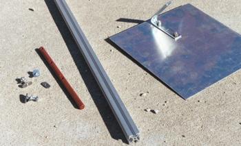
Parts for one rail:
- Rail - 1.0-inch by 1.0-inch, length as desired
- Cold Roll - 1/2-inch diameter, need at least 18 inches per rail
- 2 x 1/4-inch bolts, coarse thread, 1-inch long
- 1 x 1/4-inch bolt, coarse thread, 3/4-inch long
- 3 x rail fasteners (to fit bolts above)
- 3 x 1/4-inch washers
- 3 x 1/4-inch lock washers (split type)
- Angle bracket
- Steel Plate - 8 to 10-inches square, stainless is best
- 2 x 5/16-inch bolts
- 2 x 5/16-inch nuts with nylon inserts
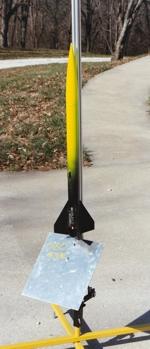
 When I made these for the club (made two),
I wanted the blast plates to be fixed to the rail. The idea was that the parts
wouldn’t get lost or misplaced and that there would be no question of how
it goes together when the range is being set up. I also wanted the deflector to
stand away from the rail at an angle to avoid burning up the bottom of the
birds, and also to keep the flames out of the rail where it will melt the
buttons. What I came up with was to purchase a pair of L-shaped brackets from
the hardware store. The brackets started out with a 90 degree angle, and I bent
them another 30 degrees to get the outward deflection I was after.
When I made these for the club (made two),
I wanted the blast plates to be fixed to the rail. The idea was that the parts
wouldn’t get lost or misplaced and that there would be no question of how
it goes together when the range is being set up. I also wanted the deflector to
stand away from the rail at an angle to avoid burning up the bottom of the
birds, and also to keep the flames out of the rail where it will melt the
buttons. What I came up with was to purchase a pair of L-shaped brackets from
the hardware store. The brackets started out with a 90 degree angle, and I bent
them another 30 degrees to get the outward deflection I was after. I first measured the distance between the holes in the angle bracket. A metal marking tool and the edge of my tool box drawer handle were used to mark a reference line along the length of the rod (much like we do when marking fin lines on body tubes.) The screw holes were measured out and the rod chucked into the drill press vice. It’s a little tricky to get the drill bit to go straight down into the round rod - it tends to walk a bit making a series of straight holes hard to drill. Either use a very short small bit to make a starter hole, or carefully tap a spot with a punch. The first hole is drilled near the top of the rod, the second spaced the distance of the holes in the angle bracket, and the third an equal distance below that. The bottom most hole wound up at about four inches from the bottom. That four inch length is what fits into the pad’s bracket. I sized these to fit to the bottom of the bracket just as the rail meets the bracket top.
The ends of the rod and the areas around the screw holes were sharp and had burrs so an angle grinder was used to round off the ends, and to gently smooth the areas around the holes. A flat spot was made around the lowest hole for the washer and screw head to fit against using a grinding point in the drill press. I then used a piece of emery paper on the ends and around the holes to smooth out those areas.
 I found that the rail also had burrs around the top, and
the edges were sharp and would mar the finish on the rockets as they were slid
on to the rod so I used the emery paper on those ends as well.
I found that the rail also had burrs around the top, and
the edges were sharp and would mar the finish on the rockets as they were slid
on to the rod so I used the emery paper on those ends as well.
The two long 1/4-inch screws were assembled with the lock washers and flat washers (in that order) through the angle bracket and then the rod with the rail fasteners threaded on a turn or two. The third shorter bolt and washers were assembled through the bottom hole. (My angle bracket has two holes, so one of the screws needs to be shorter than the other two; your mileage may vary based on your angle bracket and where you bought it.) The fasteners were then slid up the rail until the bottom one was just fully inside. The screws were then tightened with a wrench. I should note that the bottom bolt is just long enough and required a bit of effort compressing the split washer while fitting it into the slot.
The plate was marked with a center line, and a set of holes that match the other arm of the angle bracket were drilled on the line. It’s set a little higher to reach over the bend in the bracket. The edges and corners of the plates were both pretty rough, had a sharp edge, and burrs so they were rounded off with the angle grinder and touched up with the emery paper. This treatment was given to the screw holes as well. The plate was then attached to the bracket using the 5/16 inch bolts and screws.
We could have used the blast plate supplied with the Wasp pads by simply reaming out the hole a little, but I’m a little less than thrilled with a flat plate under a heavy rocket. I’ve also heard of rail buttons being melted or burned due to the motor flames forced into the channel by the deflector. The blast plate on the shorter rail is made of aluminum and some comments were made at the launch that it would be burned through quickly. It is felt that since we are launching G80s and smaller from this pad that won’t be a problem. It would certainly be a different matter if we were launching K motors, though. The longer of the two rails wound up with a plate of steel, though.
 One of the two rails were taken to the
November 2002 launch for use, but we ran into a snag. The problem was with the
square tube of the launchers - there’s a weld line along one side inside
the tube where the ends were brought together. These pads are the excellent
Wasp pads from Yellow Jacket Systems, and rated to take up 3/8-inch rods. They
will almost take a half inch one. So we weren’t able to use it that
weekend. After the launch I took the new rail and one of the pads home for
adjustments. By grinding a flat spot on the rods under the bolts they were made
to fit nicely.
One of the two rails were taken to the
November 2002 launch for use, but we ran into a snag. The problem was with the
square tube of the launchers - there’s a weld line along one side inside
the tube where the ends were brought together. These pads are the excellent
Wasp pads from Yellow Jacket Systems, and rated to take up 3/8-inch rods. They
will almost take a half inch one. So we weren’t able to use it that
weekend. After the launch I took the new rail and one of the pads home for
adjustments. By grinding a flat spot on the rods under the bolts they were made
to fit nicely.
After completion, I measured the amount of rail taken by the adapter/deflector. Configured this way, one eats about 10 inches of length. That leaves about 38 inches of usable rail for the 48 inch one, and about 86 inches of usable rail on the eight footer. What I found in practice, though, was that an eight foot long rail is way overkill for pads of this size. I also had some concern that the 1/2-inch rod would bend at the lowest screw hole under too much load. So I cut that one down to six feet of usable length. It is still a little tall even now, requiring a good stretch of a tall person to reach high enough to get the rocket on the rail without laying it down (the Wasp pads allow you to pull a pin and swivel the head down for loading.)
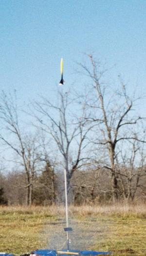
We tried again at the November 30th launch with much better luck. The photo shows my Aerotech Airspike just after the first launch from the taller of the two new rails.
If you decide to make one of these, and your pad can handle a larger diameter rod, consider using a fatter dowel and longer screws. I feel that these assemblies are suitable for the Wasp pads, but wouldn’t attempt to use them for anything larger than what the pads can already handle; larger rockets and motors require heavier equipment, please plan appropriately. Naturally, care must be taken to adhere to the pad manufacturer’s weight and size limits when launching!
While we haven’t had a lot of opportunity to use these new launch rails, I’m sure they’ll work great and get plenty of use next season.
 |
 |