Scratch Red Hot Wax Original Design / Scratch Built
Scratch - Red Hot Wax {Scratch}
Contributed by Scott Turnbull
| Manufacturer: | Scratch |
 Brief:
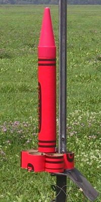
This crayon rocket was my Level 1 Certification project and features tube fin stabilization. The construction techniques allow individual tube fins to be removed and reinstalled.
Construction:
The major components in the Red Hot Wax rocket are as follows:
- 2 Crayon banks
- 1 38mm motor mount tube
- 3 5-ply Plywood centering rings
- 1 Plywood bulkhead for nose cone
- 1 Carriage bolt and nut
- 1 U-bolt for shock cord attachment to motor mount
- 1 Eye-bolt for shock cord attachment to nose cone
- 2 T-nuts for motor retention
- 12 Nuts and bolts for tube to tube attachments
- 10 Machine screws with integral washer for tube to airframe attachment
- 2 Rail buttons
- 2 Nylon spacers for rail buttons
- 2 Machine screws for rail buttons
Recently, while pondering a Level 1 certification project, I decided to do something a little different. I wanted a rocket with replaceable fins. The Tubular Crayon described on EMRR gave me a starting point. I already had a crayon bank in my project supplies. With the Tubular Crayon as a proof of concept, I set out to design my own assembly technique. With field maintenance in mind, I would rely on hardware, rather than adhesives for final assembly.
 I bought two additional Crayon banks to cut up for the six tube fins. I initially was going to use long tube fins, but after a few sessions in RockSim, I downsized them by half to 3 1/2". I used a miter box and razor knife to cut six tubes from one crayon. A seventh ring less than 1" high was set aside for later use.
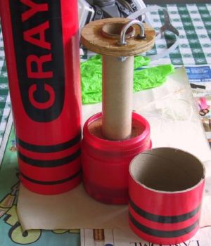
I started with the motor mount. Duly warned that the crayon bank plastic was difficult to glue to, I prepared a set of 3 rings that would be physically locked within the crayon base. I hand cut the rings with a saber saw from leftover 5-ply flooring plywood. Each was a different diameter to fit into different parts of the crayon base and airframe. It might seem that the centering rings are overly thick for a rocket of this size, but these rings are critical for the attachment of the tube fins in later assembly.
A drill chucked hole saw was used to cut the central 38mm mount holes. A Dremel barrel sander was used to tidy up the edges. Two rings would be mounted 3 inches apart to screw the tube fins into. The third ring was near the top of the motor mount to stabilize the lower airframe.
 I wanted a recessed motor mount, so that the crayon would not stand on the motor tube. I cut a large access hole into the bottom of the crayon base. I epoxied the 1" cardboard ring inside the base and pressed it against the bottom edge. This provides the recessed motor mount. Above this was epoxied the lower centering ring. T-nuts were epoxied in from above the lower ring to provide motor retention. The middle centering ring was epoxied into the coupler section of the base that goes inside the airframe. The motor mount tube was epoxied in place through the lower two rings. The upper centering ring was epoxied to the motor tube after a U-bolt was installed for recovery harness attachment.
The nosecone was fashioned by using a carriage bolt through the tip of the crayon and bolting it to a bulkhead inside the nose. An eyebolt on the bulkhead connects it to the recovery harness. Different amounts of weight can be installed on the carriage bolt above the bulkhead.
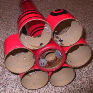
The motor mount was dry fit into the crayon. The tube fins were assembled side by side in pairs using nuts and bolts, and each pair was then screwed into the lower centering ring. Each bolted tube pair was then bolted to its neighboring tube pairs. The motor mount was not yet firmly attached to the airframe. The ability to remove the motor mount and attached fins and carry the assembly into the hardware store caused a few raised eyebrows. It helped me size the final pieces of hardware for mounting rail buttons and motor retention.
The motor mount was epoxied inside the airframe with a liberal epoxy fillet. This was near to the anticipated final center of gravity, so weight here was not a significant stability concern. The final screws were inserted through the upper edge of each tube fin through the cardboard airframe, the plastic base coupler, and finally into the epoxied middle centering ring.
One tube fin was singled out for special treatment. It received rail buttons on nylon standoffs rather than the shorter machine screws used on the other five tube fins. There was some difficulty getting the rail buttons aligned due to the tight space of working within a 4" tube. The ability to unbolt a tube fin and remove it proved very handy. The rail buttons were JBWelded to their spacers and to the inside of the tube fin. Using the rail buttons as a guide, a finger drill was used to mark where on the base to drill for the rail button screws. The tube fin was removed and holes were power drilled for the screws. The tube was reinstalled and the screws were driven in using a screw bit on a ratchet handle.
The tubular nylon recovery harness was attached to the centering ring and nose cone using quick link couplers. A 36" chute was also attached with a quick link. A Nomex sheet threaded onto the harness protects the chute.
Flight and Recovery:
I did a number of simulations of the design using actual measured and adjusted center of gravity specifications. While the design was predicted as stable with a G engine, the weight of the H engine showed the design as edging towards marginal stability. I added 8oz of weight to the nose bolt to move the CG forward.
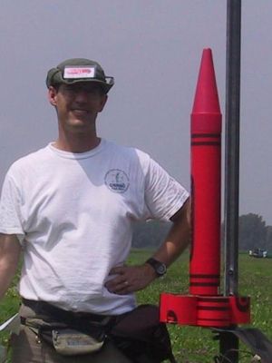
I loaded up a Cesaroni Pro38 244H153-13A after drilling out a 5 second delay reduction. After filling out my certification paperwork and alerting my witnesses, I put the RedHotWax on the rail and waited for my first high power flight. I was so nervous trying to get a photo of the flight that I botched the picture and missed the initial boost. Those Cesaroni's don't dally on the pad!
It had a little wiggle on the boost, straightened out, arced over, and kicked the chute as planned shortly past apogee. After a slightly brisk descent, the rocket was recovered within 200 feet of the pad and my certification paperwork was signed. I estimate the altitude as just under 1000 feet, just as the simulation predicted.
Summary:
This is a slightly heavy, draggy design, so don't expect any record setting altitudes on an H motor. On the other hand, you'll have no trouble watching the entire flight profile without having to ask "Has anybody got that?"
PROs: This airframe can be had for about $6 at Toys R Us stores. Add another crayon for tube stock and you get two nose cones, two bases, and enough tube for one tube finned crayon. Scrap wood, epoxy, and hardware store items complete the major assembly.
CONs: The need to run the launch rail up through a tube fin means that the rail cannot have a large stiffening structure running up the back of the rail. I had to change rail assignments in the field to accommodate the need to pass the rail through the tube fin.
 |
 |