Scratch Rumble Bee Original Design / Scratch Built
Scratch - Rumble Bee {Scratch}
Contributed by Jack Anderson
| Manufacturer: | Scratch |
Note: This is a slightly condensed version of all the information that Jack has produced for his Level 3 project. Visit his site to read the additional information and enjoy additional pictures.
 Parts
Parts
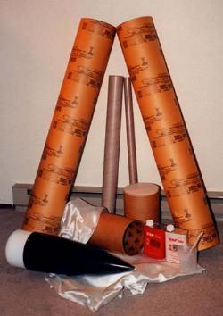
The picture to the left is most of the parts that I have purchased for this
project. The two big airframe tubes came from Eagle Hardware in the cement
section, they are the same inner diameter as a PML 7.51 inch airframe and they
sell for $3.85 each. They sell them for making cement pillars. The motor mount
tubes came from All-Hobbies as did the 7.51 inch couplers. The motor tubes are
75mm and 38mm. The fiberglass and epoxy came from TAP Plastics in Bellevue, I
have some 8.6 once cloth and some 1.4 once cloth. The nose cone is borrowed
from my LOC Precision Bruiser. The centering rings and fins were special
ordered from PML and had not arrived yet when this picture was taken.
Airframe
The first thing I like to do is get the fiberglass on the airframe. Because I
live in an apartment with no shop or garage, I do most of my work in the
kitchen. The first step in fiber glassing a tube is to cut the fiber glass
cloth down to the approximate length that you will need. Do this by rolling the
cloth around the tube and marking the cloth, allow for some overlap of the
cloth. Once you have the cloth cut, I like to suspend the airframe tube
horizontally. Ideally you could run a 2 x 2 or a heavy dowel through your
airframe and hang it across two saw horses. I have to settle for a piece of
speaker wire tied to the backs of two chairs. I prefer using speaker wire over
cord or rope because the epoxy resign does not soak into it and therefore it is
easy to untie and reuse. Once your air frame is suspended horizontally, mix up
enough epoxy to coat the entire surface. The resign that I used on this project
was a 1 to 1 mix and I used 3 ounces of each part (6 ounces of mixed epoxy).
Then spread the epoxy over the entire surface of the tube. The photo above
shows the tube just before completing this step. I use the cheapest paint
brushes I can find to spread the epoxy. You can get a 1 1/2 inch wide brush for
around $.50. You can try to clean them with acetone in between uses, but I just
throw them out and use a new one each time.
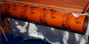 The
next step is to apply the cloth. I stretch it across the top of the tube as in
the picture. Then pat it down against the wet tube and rotate the tube as you
go. You can work out the wrinkles and air bubbles with your hands or you can
use some type of scraper or spatula. Some people like to wear surgical gloves
during this process, my hands don't seem sensitive to the epoxy and I prefer to
just use my bare hands. Of course you will want to have paper towels or a rag
handy for when you complete this step.
The
next step is to apply the cloth. I stretch it across the top of the tube as in
the picture. Then pat it down against the wet tube and rotate the tube as you
go. You can work out the wrinkles and air bubbles with your hands or you can
use some type of scraper or spatula. Some people like to wear surgical gloves
during this process, my hands don't seem sensitive to the epoxy and I prefer to
just use my bare hands. Of course you will want to have paper towels or a rag
handy for when you complete this step.
After you have worked your way all the way around the tube you can trim the cloth near the edges. There may be some places where the cloth is still dry. At this point I usually mix up a small amount of epoxy and soak the dry spots on the cloth and especially soak the seam where the fiberglass overlaps itself.
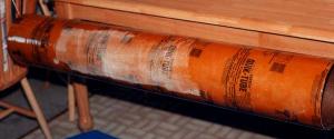
After your epoxy is thoroughly dry it should look something like this. The epoxy that you choose is very important. You don't want something that will set up too quickly and cause you to rush when working out the air bubbles and wrinkles. On the other hand you don't want to wait for days in between steps. The epoxy that I bought actually set up a little too fast for the size project that I am working on. I had about 30 minutes from the time that I mixed it until it was to sticky to work with. Fortunately I was able to get everything finished before it set up. I always let my fiberglass cure for 8 or 9 hours before moving to the next step. You don't want it to be even the slightest bit tacky.
After your epoxy is dry you need to trim the edges with an exacto knife or box cutter. Next sand the entire surface of the tube. Most of it can be a quick couple of strokes. The edges of the tube and the seam where the fiber glass overlaps itself will need a little more attention. By sanding the edges of the tube you trim off any fibers that may be sticking up. This is not the final surface and therefore does not need to be glassy smooth. It fact with the 8.6 ounce fiberglass that I used here that would be very unlikely. You can clearly see and feel the weave of the cloth still.
 Once you
have the tube sanded, it is time to put it back it the horizontal position. At
this point I mix up another batch of epoxy and paint it on. The picture shows
the tube just before finishing this coat of epoxy. Like before, you will want
this to dry for 8 or 9 hours before the next step. Next is more sanding. I
finally broke down and bought myself an orbital palm sander (best $30 I ever
spent). This time you will want to sand the tube thoroughly. If you are only
planning on one layer of fiberglass, this will be your finish surface so you
will want to sand it with 100 grit paper to take down any imperfections and
then again with 220 or finer before painting. For this project I will apply a
finish layer of fiberglass on top of this one.
Once you
have the tube sanded, it is time to put it back it the horizontal position. At
this point I mix up another batch of epoxy and paint it on. The picture shows
the tube just before finishing this coat of epoxy. Like before, you will want
this to dry for 8 or 9 hours before the next step. Next is more sanding. I
finally broke down and bought myself an orbital palm sander (best $30 I ever
spent). This time you will want to sand the tube thoroughly. If you are only
planning on one layer of fiberglass, this will be your finish surface so you
will want to sand it with 100 grit paper to take down any imperfections and
then again with 220 or finer before painting. For this project I will apply a
finish layer of fiberglass on top of this one.
After sanding the tube I get it ready for some more epoxy. This time the fiberglass that I am using is only 1.4 ounce cloth. It will cover up any pits from the first layer. The finer cloth is more difficult to work with than the heavier weaves. It is more prone to wrinkling, but it sure gives you a nice surface. I follow the same steps as before. Paint on the epoxy and work the cloth as you rotate the tube. I do make sure that the seam from this layer is not the same place as the first, just to add a little strength and it helps to cover up the first seam.
After applying the finer layer of fiberglass cloth, I sanded the entire tube again after it had cured for 8 hours. Next I applied yet another coat of epoxy as I had done with the first layer. After that coat of epoxy was cured, I sanded the entire surface of the tube with both 100 grit and 220 grit sand paper. The total length of the rocket will be 9 foot 10 inches.
 Motor Mount
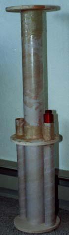
Here is a picture (right) of the motor mount assembly. There is a central 75mm
motor with two outboard 38mm motors. I plan to set things up so that the 38mm
motors can be air-started. In this picture I have epoxied the top centering
ring and the middle ring in place, but the bottom centering ring is just in
place to align the tubes (not epoxied yet). I also used some fiberglass to give
additional strength to the motor mount assembly. The 38mm tubes are woven to
the 75mm tube with fiberglass and the top centering ring is fiber glassed to
the 75mm tube. For the picture I have inserted a 18 inch Dr.Rocket 38mm 1080
motor.
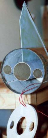
Here is a picture (left) with the motor mount assembly inserted and the first fin in place. The red wires that you see run from the electronics bay to the rear of the rocket and will be used for air-starting motors. As you can see the bottom centering ring is now removed so that I have access to the fin tabs. I have pealed off the inner layer of paper from the cement form tubes that I got at Eagle, because they have a wax coating on the inside which would make the bond between the centering rings and the airframe weaker. I have also cut slots into the airframe so the fins can slide through and attach to the motor tube. The fins are .093" G-10 fiberglass from PML. I use a piece of masking tape stretched from the tip of the fin down to the airframe to hold the fin where I want it while the epoxy dries.
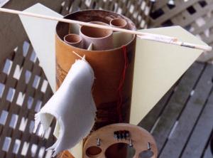 Here is
a picture just before I begin reinforcing the fin joints. I have made a long
handled paint brush (pictured) and cut six pieces of fiberglass to size. The
plan is to paint the full length of the motor mount tube, fin tab, and inside
of the airframe with epoxy and then using the paint brush smooth the fiberglass
cloth inside the rocket.
Here is
a picture just before I begin reinforcing the fin joints. I have made a long
handled paint brush (pictured) and cut six pieces of fiberglass to size. The
plan is to paint the full length of the motor mount tube, fin tab, and inside
of the airframe with epoxy and then using the paint brush smooth the fiberglass
cloth inside the rocket.
Electronics Bay
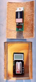
This picture (below-left) shows the electronics bay on the payload section of
the rocket. There is a rectangle cut out from the airframe, right behind that
is a coupler tube with a smaller rectangle cut out. The piece that was cut out
from the airframe acts as a door to seal off the electronics bay when the
rocket is in flight. I will be using two altimeters during the flight of this
rocket. First is an Olsen Electronics M-2 which is mounted inside the
electronics bay on a piece of plywood which is held in place with epoxy, second
is a Blacksky AltAcc which is mounted to the door of the electronics bay.
 To make sure that the
forces of the parachute opening would not pull the bulkhead plate out of the
rocket, I reinforced those attachments with fiberglass after using a standard
fillet of epoxy first. The fiberglass covers about 4 inches of the airframe
above each bulkhead plate, and also covers most of the bulkhead plate. There
are two small holes in the bottom of the bulkhead where the wiring from the
deployment charges will eventually be routed into the electronics bay.
To make sure that the
forces of the parachute opening would not pull the bulkhead plate out of the
rocket, I reinforced those attachments with fiberglass after using a standard
fillet of epoxy first. The fiberglass covers about 4 inches of the airframe
above each bulkhead plate, and also covers most of the bulkhead plate. There
are two small holes in the bottom of the bulkhead where the wiring from the
deployment charges will eventually be routed into the electronics bay.
The aft centering ring was cemented in place with epoxy. Six bolts which are anchored with T-nuts and will be used for positive motor retention. There is a wiring block which is wired to the second electronics bay where the timer will be located for air-starting the 38mm outboard motors. The second electronics bay will be located in the coupler at the top of the booster section of the rocket, but is not finished at this time.
Pictured (above-right), is the entire rocket with the altimeter bay door open after the first coat of primer. I think I am going to need a ladder at the launch pads to activate those altimeters. So far with no motors and no parachutes, the rocket weighs in at 21 pounds and is 9 foot 10 inches tall.
 Finish
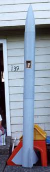
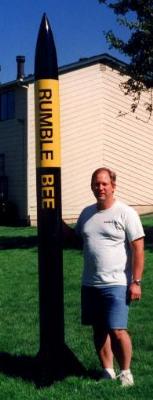
Here is the finished painted project. I was planning on launching it on the
Bonneville Salt Flats at Hellfire 6, but was unable to ship it to Utah because
it was too big for UPS to ship the smallest section. Lesson learned : If you
plan to ship a rocket to attend a launch out of state, make sure it will fit
into a box that can be shipped. UPS will take a box as long as the width + the
height + the depth = 130 inches or less. The bottom half of this one needs a
box 20 X 20 X 57, which is 7 inches too much for UPS. The next cheapest shipper
that I found wanted $205 to send it, if it was 7 inches shorter UPS would have
sent it for $23.
LEVEL 3 - PENDING FLIGHT
Date
Where
Rocket - Scratch Rumble Bee
Weight -
Motor -
Altitude
 Launch
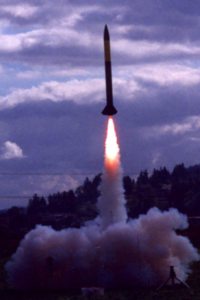
This is the maiden launch of the Rumble Bee at Monroe Washington. The motor I
chose is the biggest one allowed on this field... a K-700. The Blacksky AltAcc2
altimeter that I used reported a maximum altitude of 2916 feet. The flight was
perfect, straight and loud!
The Rumble Bee as it descends on it's 44 inch PML drogue chute, then the Rocketman R14C deployed to bring the Rumble Bee down gently after it's first flight. I am already looking forward to the day I can bring it out to a bigger field and put an L-1120 in it.
I was planning on flying it on an "L" motor at Hellfire in Utah on Sept. 14, 2001. But as we all know the events of Sept. 11, 2001 stopped all rocketry activity for awhile.
I finally flew it on an "L" motor last summer at Hellfire 8 (Aug16, 2002) using an Animal Motor Works Green Gorilla L1060 plus air starting two Aerotech Redline I366 motors about 1 second after lift off. The effect was a green flame changing to orange and eventually pure red. I plan to do my Level 3 flight next summer.
 |
 |