Scratch Good Ship Manatee Original Design / Scratch Built
Scratch - Good Ship Manatee {Scratch}
Contributed by Charles Delaney
| Manufacturer: | Scratch |
Brief: Construction: Parts List: EDITOR'S NOTE: At this time BRS can only get the BT60 to BT56 transition, therefore, to build this kit from all parts readily available from BRS: Change all the BT55 references to a BT56, the transition from BT60 to BT56 transition. The size difference between the BT55 and BT56 is very minimal. This change shouldn't have any affect on the design. Although wood glue should be sufficient, I used 5 minute epoxy due to it's strength and fast curing time. If the BT 55 tube is not going to be used for a payload section the nose cone and transition piece can be glued to it and set aside until time to paint it. However it lends flexibility if the nosecone is detactable. NOTE: my transition piece was a custom balsa piece for a different rocket and weighs about 10 grams more than the Estes part. It might be a wise precaution to add that extra weight to the nosecone to keep the CG from shifting too far back. Assemble motor mount and centering rings and glue it into place in the BT 60 tube. I placed the mount flush with the end of the body tube, but extending it 1/4" out would be ok too. Mark the fin placement lines. The fins are the most complex parts and proper alignment is _very_ important if the rocket is to be flown clustered. After glueing the BT 20 nosecones and tubes together, test fit them into their notches in the fins. All should extend equally behind the fins, trim as needed. Sand fins' edges for desired shape before glueing the pods into place. Again, be mindful of getting a good alignment. After the fins have been attached to the BT 60 tube take the launch lug and cut it in half. Take one half and glue it near the bottom of the tube, against one fin. Near the upper edge of the same fin glue the other half, making sure both are lined up with each other. It goes without saying that if the fin was properly aligned when glued in place the launch lugs will be parallel to the long axis of the rocket. This wider LL spacing is another stability precaution against cluster misfires. Shockcord attachment is a matter of preference. I prefer an anchoring system similar to that used by LOC Precision kits so the cord can be replaced at need. There is no such thing as too much shockcord, especially on a rocket that might go very high and/or fast. The more cord, the more shock it will absorb so nothing tears loose. The shortest one I use is 6' long. Finishing: The colors were chosen because no self respecting sci-fi spaceship worth it's blaster ray would be anything but silver. The red was chosen for contrast to increase in-flight visibility and to give the illusion of it still being hot from re-entry's heat. Most early ships' design/paint schemes tended to be bold but not very detailed, so I did the same here. Flight Tests/Motor Recommendations: Obviously clustered flights should have longer delays for the primary motor than the above recommendations. Pod motor delays should be shorter than but close to the primary's delay as a precaution against becoming low altitude projectile hazards as they eject. The first flight was on a single D12-7. Arrow straight and picture perfect, giving a "slow" majestic lift-off. No single E9 flights will be attempted after seeing the slow lift-off of the single D12, E's will only be used in clusters. Second flight was a "destructive testing" flight with a purposeful cluster "misfire". Motors were a D12-3 and a single A6-5. The D12's shorter delay was in case of problems the flight would be cut short. Again the Manatee gave a perfect flight without a hint of instability. The first full cluster flight was on a C11-7 and three A8-5's. This was one of two cluster configurations that was expected to give the most trouble. The C11 due to it's lower power, and the E9 due to it's lower thrust. There turned out to be another problem, the launch system wasn't able to provide enough current to fire 4 motors at once and only the C11 lit. As expected the C11 wasn't powerful enough when hampered with the weight of 3 unlit motors, fortunately damage was limited to a broken fin that was field repaired for another try. Changes were made in the launch system to increase current so the 2nd attempt was successful, though one outboard motor didn't light, and the Manatee landed safely. As of this writing an E9 cluster has not been tried due to the motor being out off stock at the local hobby shop. However, based on the above 4 flights, the following assumptions seems reasonable. The C11-3 and D12-5 are viable single motors while an E9 likely is not. In clusters the C11 should remain a short delay motor, due to it's lower power, in case of cluster misfires. In general do not use a longer delay if using A motors in the cluster. The D12 is the optimum motor for all applications. Cluster launches _are_ impressive. The altitude predictions were overly optimistic. It's not known if there will be another launch where the repaired Manatee can be flown before the contest dead line. Thus this might be all the information that can be provided. In general the design has proven very stable in flight with the only problem being the reliablity of getting all motors to ignite. This re-enforces the opinion that this is not a rocket recommended for a first cluster attempt. One possible solution come to mind, to have the central motor on it's own circuit separate from the outboard motors so to increase it's reliablity. This assumes a launch system that can handle simultaneous launches, such as with drag races. An upscale of the design so it could carry electronics to control recovery in case of mishap might be fun to try too (G40 and 3 E9's!!!!). Summary: Cons - Not a rocket I would recommend for your first cluster flight. Mis-alignments in the fins/pods could cause "interesting" flight paths. Make VERY sure your launch system can provide adaquate power for cluster flights. It might fly too high and never come back because it "landed in Oz."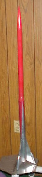
I like several types of rockets. High performing ones, odd/fun/uncommon designs, and classic 50's sci-fi types. "The Good Ship Manatee" has a bit of all of them in it. The rocket can be flown clustered since the fins' pods will hold 3-18mm motors. As a safety redundancy the motors are canted towards the CG (as in the Duece and Tres cluster kits) if there is a failure to ignite all motors. The rocket's name comes from the filk song by Leslie Fish. It fits.
To make this rocket you need:
The rocket was coated with 20-minute finishing epoxy, wet sanded, painted, and then another coat of finishing epoxy. The fins and pods recieved 3 coats before painting. This was to both seal the wood grain and to allow the epoxy to "wick" into and seal any gaps and imperfections in the joints. Because epoxy was the adhesive no filleting was deemed needed, thus giving smooth, sharper looking joints.
The computer sims recommend the C11-3, D12-5, and E9-6 for single motor flights. Predicted altitudes range from 350' on a single C11 to 1800' for a full cluster of an E9 and 3-C6's.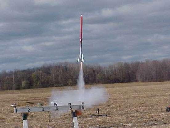
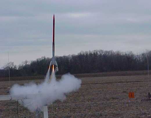
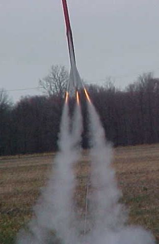 12/6/04 Update: Yesterday's launch was the final flight test for the Good Ship Manatee. Planned were two full cluster flights. One D12/threeC6 and one E9/threeC6. The D12 flight was first since the E9 flight would triple the total power of any previous flight. The flight was very showy for spectators as the outboard motors left a triple spiral of smoke as the Manatee spun on accent. It's assumed this was caused by a slight misalignment of the outboards, but it wasn't a bad thing given the visual effect. It was at appogee however it was discovered the central D12 had failed to ignite and the rocket did a very impressive lawndart since the outboards alone still provided 50% more power than any prior flight and had sent the Manatee the highest yet. The payload section was destroyed, absorbing the bulk of the impact and sparing the booster section which, though damaged, is repairable. Obviously the E9 flight was scrubbed.
Pros - Flexible in the range of motors it can use, to adapt to local flight conditions, while still giving good performance across the board. Cluster flights put on a show for spectators. It should be able to mount an Estes MaxTrax altimeter for those wanting to know how high is goes.
Sponsored Ads


 |
 |