Scratch Silver Streak II Original Design / Scratch Built
Scratch - Silver Streak II {Scratch}
Contributed by Eric Maglio
| Manufacturer: | Scratch |
 Brief:
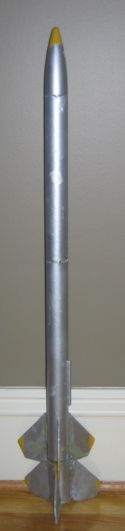
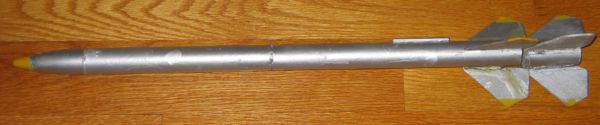
The Silver Streak 2 is a 2- stage rocket built with Estes parts. It is a high
performance kit, capable of reaching high altitudes with very small engines.
Parts:
- Nose cone Estes - Estes - BNC-50K
- Material: Polystyrene PS
- Nose shape: Hollow Ogive, Len: 2.750 In., Dia: 0.976 In. Wall thickness: 0.125 In.
- Body tube Estes - EST 3086 - BT-50
- Material: Paper OD: 0.976 In. , ID: 0.950 In. , Len: 21.000 In
- Parachute Estes - 12 in - 12 in. plastic
- Material: Polyethylene LDPE 1 parachute
- Shape: 6 sided
- Launch lug Estes - ESTES 2328 - LL-1/8
- Material: Paper OD: 0.188 In., ID: 0.169 In., Len: 2.000 In., Loc: 16.250 In.
- Custom Fin set - Custom Click for Pattern
- Material: Balsa 3/16" thick
- Booster Body Tube Estes - EST 3086 - BT-50
- Material: Paper OD: 0.976 In. , ID: 0.950 In. , Len: 3.000In.
- Booster Custom Fin set - Custom
Click for Pattern
- Material: Balsa 3/16" thick
- 2x Estes A-C engine Motor Mount Kits
- 1 Estes Shock Cord
- 1 Estes Shock Cord Mount
Construction:
As this is a fairly small rocket, I recommend Elmer’s Carpenters Glue for construction.
- Motor Mounts: Glue the Green Thrust Ring the inside of the yellow body tube, so it is flush with the top of the tube. Next, glue the card-like Centering Rings ½ inch inside from either end of the yellow body tube. The mount should now fit into the BT-50 body tube. Trim the centering rings if necessary. Then, repeat these steps on the 2nd motor mount, but omit the Green Thrust Ring.
- Motor Mount Installation: Spread glue with your finger about 1 inch from the bottom of the 21 inch long body tube. There should be an even bead of glue around the inside. Nest, slide in the motor mount with the green thrust ring into the tube, thrust ring side first, until the yellow tube is flush with the bottom of the body. Let dry and repeat on the 2nd motor mount and 3 inch long body tube.
- Tube Marking: According to the RockSim file or other source, mark the body tube. This is done by drawing 3, 3 inch lines from the bottom of the 21 inch body tube, each line being evenly spaced apart. Next, draw a 2 inch line 2 inches from the bottom of the tube and between 2 of the fin lines. Also, draw the longer fin lines the same way on the booster tube.
- Sustainer Fins: You will now need to install the fins. Glue 1 fin to
one of the 3 inch lines on the body tube, and make sure it is completely
straight. Then, let that fin dry and repeat the steps with the other 2 fins.
You should get a rocket that looks like this, with each fin evenly
spaced:
- NOTE: on Fins: The fins look different in the template because they were rounded when finished. In my plan, the fins do not hang off the bottom of the rocket as in real life because I had encountered some trouble with this and had to mount the booster backwards.
- Booster Fins: Repeat step 4 to glue the fins to the booster. Again, the fins should be completely straight and evenly spaced.
- Launch Lug: Apply glue to the launch lug and place it on the remaining line on the longer body tube. Use a square to make sure it is straight and level. Located 16.250 In from the nose cone.
- Shock Cord Mount: Smear a generous portion of glue on the shock cord
mount and place 1 end of the shock cord on it, through all sections on the
mount. Then fold section 1 over the shock cord and section 2 over section 3. it
will look like this:
- Shock Cord Installation: Apply glue to the bottom of the shock cord mount. Next, place it in the top of the sustainer body tube, about 1 inch from the top, with the shock cord coming out of the top of the rocket. Press down firmly until the glue is tacky, then let it dry.
- Parachute Installation: To install the parachute, first tie it to the eye loop of the nosecone with a double knot, and then tie the nose cone to the end of the shock cord. Your Silver Streak II is now complete.
- Motor Installation for 2 stage rockets: For a multistage rocket, the booster stage must always be a B6-0 or C6-0. First, get a booster engine and a sustainer engine of any type, and stack them, booster engine first. Then, cut a piece of masking tape and loosely tape the two engines together. Finally, slide the sustainer engine into the sustainer engine mount, and slide the booster over the booster engine.
Flight:
This rocket flew better than expected. It flew very high on a small engine combination, and also very high on a single engine. It was flown twice at a local field, and once at CATO rocketry club. It also flew successfully with both the single and multistage configurations. I have no pictures of the launch, but there will soon be one at: http://catorockets.org/cato95/cato95.html - These will be copied and added to this contest entry soon.
| Date |
Altitude |
Separation |
Deployment |
Motors |
| 10/9/04 |
600+ ft |
Good |
On time |
B6-0, B4-2 |
| 10/9/04 |
500 ft |
N/A (single) |
After Apogee |
B6-4 |
| 11/20/04 CATO Club |
650+ft |
Good |
On Time |
B6-0, B4-2 |
 |
 |