Scratch SilverBelle Original Design / Scratch Built
Scratch - SilverBelle {Scratch}
Contributed by John Thompson
| Manufacturer: | Scratch |
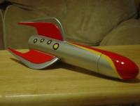
Brief:
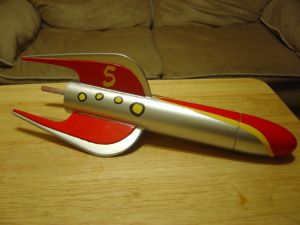
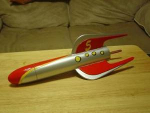
Built for the Design This Spaceship Contest. This is a single staged, dual 18mm clustered rocket built from an Estes
Baby Bertha kit.
Parts List
|
Part |
Part Number |
Quantity |
Length |
|
Nose Cone |
1 |
||
|
Shock cord |
1 |
18 inch |
|
|
Parachute |
1 |
12 inch |
|
|
Body Tube |
1 |
||
|
Balsa |
1 |
3/16 thick |
|
|
Balsa |
1 |
1/8 inch thick |
|
|
Engine Tube |
2 |
2.75" |
|
|
Thrust Ring |
2 |
18 mm diameter |
|
|
Centering Ring |
2 |
18mm to BT 60 |
|
|
Retainer Clip (Optional) |
2 |
2.75" |
|
|
Launch Lug |
1 |
2" |
**Note: Engine parts listed here are for building a 2x18mm cluster model. Part numbers and quantities will vary depending on how you build the model.
Assembly Instructions
The following instructions are for building the SilverBelle from an Estes™ Baby Bertha kit. The pre-cut fins and engine mount will not be used, unless a single 18mm model is built. The single engine mount will be replaced using a 2x18mm cluster mount. New fins will be cut using the fin patterns supplied in these instructions.
Engine Mount Assembly (2x18mm Cluster)
Begin the engine mount assembly by gluing one of the green Thrust Rings into one end of the blue Engine Mount tube. The Thrust Ring should be flush with the end of the engine tube.
Measure ¼ inch down the engine tube, from the same end as the thrust ring, and make a mark. Make a small cut through the tube at this mark using a hobby knife. Find one of the metal engine retaining clips, and place the end that is bent 90° into the cut you just made.
Run a bead of glue around the middle of the engine tube. Find one of the black, or dark grey, rings, slide it over both the engine tube and engine retainer clip and through the bead of glue. Adjust the engine clip as needed to keep it straight. Allow the glue to dry
Repeat procedure for second engine tube.
Take one of the Cluster Centering Rings and slide it over the end of both engine tubes with the green thrust ring. The centering ring should butt up against the engine retaining clip. Create a glue fillet around both sides of the centering ring. Allow the glue to dry.
Measure 1 inch down on the opposite end of the engine tubes and make a mark. Slide the second centering ring over both tubes and retaining clips to the mark you made. Create a glue fillet and allow to dry.
**Note: If you are having trouble sliding the centering ring over the retaining clips, make notches in the centering rings to allow the rings to slide over the clips.
Once the glue has dried on the engine mount assembly, place a liberal amount of glue to a Q-Tip or a scrap piece of balsa, and spread the glue, as far as you can reach, all around the inside of one end of the body tube. Slide the engine assembly inside the body tube, but not all the way to the second centering ring. Spread a liberal amount of glue just inside the end of the body tube, and then slide the mount the rest of the way into the body tube, until the engine tubes are flush with the end of the body tube. Create a fillet on the outside of the rear centering ring and allow glue to dry.
Engine Mount Assembly (Single Engine)
If you plan on using only a single engine in the build, follow the instructions included in the Estes Baby Bertha TM kit.
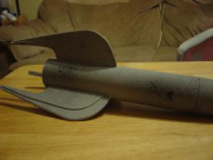
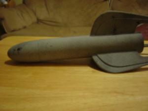
Fin Installation Instructions
Make three marks on the body tube, 120° apart from each other, on the same end as the engine mount, to locate where the fins are to be mounted.
Place the body tube against a door frame and draw three straight lines up the tube using the marks as a starting point. If you have a Fin Alignment Tool, you can use this as well.
Cut the three large fin set out of the material of your choice. Balsa is used in these instructions. Spread glue on the root edge of one fin and place the fin on one line on the body tube. Sight down the leading and trailing edges of the fin to make certain the fin is straight. Allow the glue to dry and repeat for the other two fins.
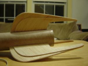
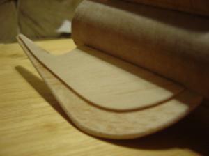
Cut the six small fin set out of 1/8 inch balsa. Attach one small fin to both sides of the large fin, creating a sandwich. Make certain to leave about a ½ inch gap between the leading edge of the large fin and the leading edge of the small fin. This will create a "step" look to the fin. Repeat for the other fins.
Launch Lug Placement
Attach the launch Lug to the rocket by spreading a small amount of glue on the bottom of the launch lug and placing it on the body tube. The launch Lug should be close to the center of the body tube, and centered between two of the fins. Sight down the launch lug to make certain it is straight along the centerline of the body tube.
Shock Cord Mount Assembly Instructions
Cut out the tri-fold paper shock cord mount and fold it on the dotted lines. Unfold the mount and spread glue on the smallest section of the shock cord mount.
Place one end of the elastic shock cord in the glue and fold the mount, with the shock cord, to the second section. Press firmly to spread out glue. Spread glue on the third section of the shock cord mount and fold over the second section and elastic shock cord. Press firmly to spread out glue.
Once all three sections have been glued to each other, bend the mount into a U shape so it will be easier to glue to the body tube. Tie the other end of the shock cord to the nosecone. Secure shock cord to the nosecone with CA if desired.
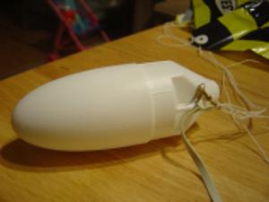
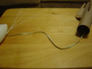
After the glue has dried, spread glue on the bottom of the paper shock cord mount and place it about 2 inches inside the opposite end of the body tube from the engine mount. Press gently but firmly to ensure proper adhesion to the body tube.
Parachute Assembly Instructions
Assemble the shroud lines onto the parachute according to the instructions, if the shroud lines are not already attached to the parachute. Attach the parachute to a snap swivel by pushing the shroud lines through one end of the swivel and creating a loop. Slide the parachute through the loop and pull tight. Attach the other end of the swivel to the nose cone.
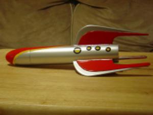
Painting your SilverBelle
The SilverBelle’s paint scheme is silver with red trim. However, you may paint the rocket any color you wish.
Start out by filling the balsa and tube spirals in the technique of your choice. Prime the rocket using a sandable, automotive grade primer. Take some flat black paint and just "dust" the entire rocket to give the rocket a "splattered" look. The flat black paint will show all the low spots, spirals, and wood grain. Allow the primer to dry for at least 24 hours.
Sand all the flat black paint off using medium grit sandpaper, such as 220 or 240 grit. Clean off all sanding residue and oils from your hands using Windex. Re-prime the rocket and "dust" it again with flat black paint. Allow the primer to dry for at least 24 hours. Sand all the flat black paint off using fine sandpaper, such as 320, 400, or 600 grit paper. Clean off all sanding residue and oils from your hands using Windex. The ammonia in Windex will remove most contaminates, and will leave the rocket with a clean surface for painting.
Paint the entire rocket with a silver base coat. Silver paint "runs" easily, so apply the paint using light coats. Allow the base coat to dry for 24 hours, then mask off the areas to be painted red.

Scuff the areas to be painted a different color with a green scuff pad found in most grocery and hardware stores. "Scuffing" up the paint creates scratches the new paint can adhere to. If the base color is not sanded or scuffed up, the paint on top will peal off.
To paint the nose cone, you should use tape that will stretch so you get nice curves. I didn't have any on hand so I had to improvise. Once that part is dry, take a touch-up brush and some yellow paint and paint the yellow trim around red on the nose cone.
For the "port holes", I just cut out holes in masking tape with a razor blade and used a touch-up brush for both the yellow and black trim.
Launching your SilverBelle
If you built the SilverBelle using only one engine, prep the rocket as with any other single engine rocket by inserting the motor, igniter, and wadding. Fold the parachute according to your preferred method and insert into the body tube. Slide on the nosecone and you’re ready to go.
If you built the SilverBelle using a cluster mount, prepping the rocket is the same. However, you will be using two motors and two igniters. Insert the igniters into each motor and use a plastic plug to hold the igniters in place. Take one wire from each igniter and twist together. Do the same for the other two wires. Attach the clips to the igniter wires as you would with a single motor rocket.
Flight and Recovery:
The first flight was less than spectacular. I prepped the rocket with two C6-5s and headed out to the launch pad. The
Range Officer pressed the launch button, the rocket went up about an inch, then sat on the pad with a beautiful flame
coming out of each motor. The tips of the fins got pretty cooked, and everyone, including me, got a good laugh. The
Range Officer asked for the motor to check and see if these were from a bad batch.
The second flight was much better. I loaded up two B6-4s and headed out again. This time it left the launch pad and had a good flight. It weathercocked a bit but recovered fine.
The third flight was on two C6-5s from another batch. It weathercocked again but still had a good flight. The parachute got a little cooked from the ejection charge and didn't fully open. It broke a fin tip on landing.
I have since repaired the fin tip and have flown it twice more. The last flight had separation of the shock cord from the body tube. All parts have been recovered and it is ready for its next flight.
Summary:
The main pro to this rocket is its retro style and two engine cluster. This is the first time I have ever launched a
cluster, so I was always worried about one motor not firing. Luckily, both motors have fired on all flights.
I would say the main con to this rocket are the fins. They extend past the rear of the body tube and will break if there is a parachute failure.
 |
 |