Scratch Snap Dragon Original Design / Scratch Built
Scratch - Snap Dragon {Scratch}
Contributed by Jimmy Yawn
| Manufacturer: | Scratch |
Jimmy gave permission to reproduce his Snap Dragon webpages on EMRR. Thank you, Jimmy.
Snap Dragon
Scratch-Built Model Rocket
Part 1: Intro and Overview
It delights me that one can buy such a vast array of rocket parts nowdays. So many suppliers, so much good stuff, so little time. Nose cones, G10, phenolic tube that fits standard motors....
And I've learned a lot from buying kits and building them. Like how to put an airframe together. How to design it so that it is stable. How to finish paper and balsa so it looks like polished metal.... Every kit has something new to teach me.
But I have a persistent character flaw that compels me to do everything myself, and then some. Good thing. My personality is of the type that deals with emergencies well. So well, in fact, that I have developed habits that tend to create them. Unfortunately, that's not a joke. Procrastination, for instance. It's crude and common, but remains a very effective technique for creating emergencies. I use it a lot. No amateurcrastination forme, I am a pro!
For instance. Back in October I had scheduled a session of Rocket Science 101 through Community Education. A few days before the class, I went to the storage room and finound my box of Estes Alpha kits. It was empty. I should have ordered another box of them from Dennis back when I signed the contract to teach. Oh, well. I can always go buy them at retail. What's money for, anyway?
Two days later I went to Mall Wart and and wound my way to the rocket department to find the precious Alphas. They had some boxed almost-ready-to-fly kits, complete with launch controller and stand, but when I looked at the wall where the not-nearly-ready-to-fly kits had been, there was other, non-rocket stuff. The kits were gone! No Alpha kits, nor anything like them on display.
Not to panic! (well, maybe a little panic.) I can do this. There is a way. Over the years I have made a number of model-rocket-like airframes from stuff lying around. I had been thinking of consolidating the better bits into a standard model, and here is an opportunity with a pitchfork.
These pages are a tribute to the students of that class, who provided me the motivation to develop this model, a chance to observe real people building them, and to test-fly a number of them with commercial rocket motors. It is a documentary of some things I learned from making these "kits," and even more I gained from the participants themselves. Thanks guys!
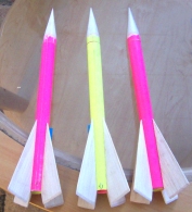 |
Now the rocket has a name! Ken, of Delanco NJ made several of these rockets using colored posterboard for the body tubes. His kids chose the colors, and his daughter Kristen gave them a clever and charming name. So with her kind permission, I hereby christen this rocket model the "Snap Dragon." Thanks, Kristen! |
 |
Procedure
 |
Body Tubes Made from posterboard and spray glue, they are quick, cheap, easy, and sturdy. Can be made lighter, at the expense of some sturdiness, or heavier, for greater strength. This technique is adaptable to many other rocketry uses, such as inhibitor tubes, case liners, and small motor casings. |
 |
Nose cone Sure, it's nice to have a wood lathe. But you don't really need one to get started. These cones can be "turned" with agile fingers from a 3x5 card, and are reinforced with epoxy. For what they lack in aerodynamics, they make up in simplicity and strength. |
 |
Fins I use a simple, functional design, subject to aesthetic and perhaps aerodynamic improvement. Includes making and installing the launch lugs. |
 |
Body Covers An easy way to create a fancy "paint job" for your rocket. |
 |
Finalizing Thrust ring, shock cord mount, recovery streamer, motor retention, and launch video. |
 |
Rocket Science 101 Photos of the October class launch, where this model was tested a number of times. Everyone in the class assembled at least one rocket, some made more than one. On launch day, they were flown using Estes motors. Except for some ejection failures, they all performed well and proved sturdy enough to survive a "lawn dart" recovery to fly again. I believe that my new motor retention system will solve the ejection problem, we shall see.... |
 |
Gallery Here's one by Geoffrey Andrews which he has named Moonstone. I like that name - it matches the colors well. The tube is carbon fiber, both lighter and stronger than the paper tubes I am using. This one should really fly. Thanks Geoffrey! |
Part 2: Airframe Body Tube
Made from posterboard and spray glue
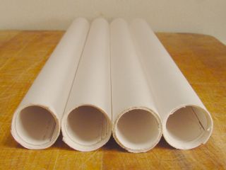 |
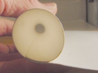
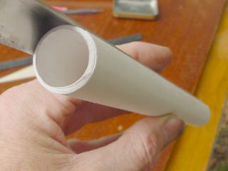
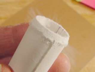
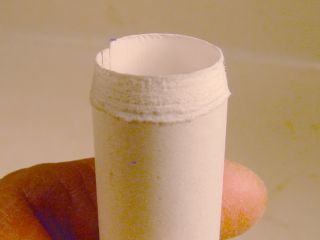
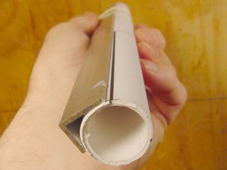
Tubes are made from posterboard, sprayed with glue, and rolled around an appropriately-sized dowel which has been covered with a relatively non-stick material. Inside diameter is a little over 3/4 inch, outside diameter just under 1 inch. Length is 11 inches, weight is 25 grams. It took about 5 minutes to make these four tubes, at a total cost of about 50 cents. |
Materials:
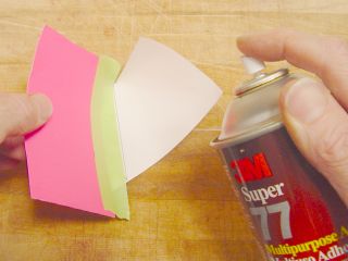
There are three essential materials, posterboard, double-stick adhesive tape, and 3M Super 77 spray glue.
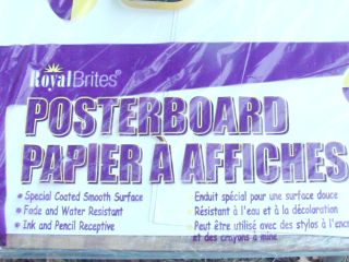 |
Primary material: posterboard. This kind is easily available here. I can buy it at the supermarket for $0.59 per sheet, or at the office supply store in packs of 10 sheets for about $4.00. Each sheet is 22 inches wide by 28 inches long. Measured with a micrometer, it is 0.012 inch in thickness. One sheet will make four body tubes. I have found many uses for this stuff lately, inhibitor tubes, case liner tubes, motor casings, epoxy mixings..... Alternative: One can use plain copy paper to make tubes like these. It would take 4 or 5 sheets of copy paper to make one of these tubes. When made with Titebond glue, these are very strong, although not always very straight. |
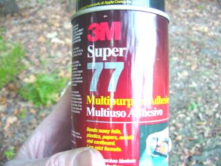 |
3M Super 77 Spray Adhesive. Guess you could have read that from the can. This is a medium-weight spray glue which works very well with paper and light wood adhesion. It costs about $7.00 per can, and is available at most hardware stores here. Advantages:
Alternatives: I have used white glue and water-based wood glues like Titebond for years in making such tubes. I still use Titebond for motor casings, as it makes for a stronger tube. 3M General Purpose 45 spray adhesive works OK. It's not quite as tacky as 77 so is a little more difficult to use for nose cones. 3M High Tack 76 is a much thicker, heavier glue that shoots out of the can in stringy blobs. It might be good for gluing plastic laminate onto countertops, but it is not suitable for this purpose. Other spray adhesives may work for this project, but these are the ones I have tested. |
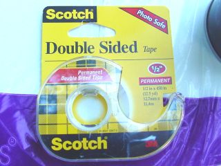 |
Double-stick tape is sticky on both sides. One of its more common uses is for mounting photographs in albums. How is it useful here? Well, Super 77 is a contact cement. It adheres immediately. If you spray any part of the posterboard that will contact the rolling dowel, it will glue to the dowel and won't slip off without a struggle. So the first turn of the roll is secured with tape instead, then the remaining posterboard is sprayed with glue and rolled up. Alternative: You can mask one side of the sheet and spray only the part that needs to be glued. This might actually be the better technique, see below. |
By the way... this tube-making technique is good for casting/inhibitor tubes as well. I used it in making grains for the Big Sugar launches recently, and in the tidy tubes for my 38mm loads.
Doing it
A few tools are needed, a ruler to measure, scissors or sharp knife to cut, and three wooden dowels. A cork-backed steel ruler is really nice, as it can be used as a straightedge for cutting, and it does not slip as easily as most rulers.
The dowels should be a foot to 14 inches long, round, straight, and smooth. If they are rough, sand them smooth.
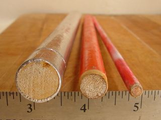 |
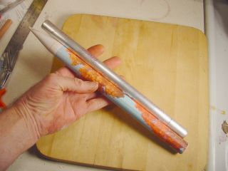
Dowel sizes are: 3/4 inch diameter, for making the body tubes themselves. 1/2 inch diameter, for making coupling tubes 1/4 inch diameter, for pre-rolling the posterboard The two larger dowels should be covered with something that makes them less attractive to glue. In the photo, note that the largest dowel is covered with Nashua 324 aluminum foil duct tape, giving it a metallic look. The 1/2 inch dowel is covered with red plastic-wrap. Both work OK. The 1/4 inch dowel is not covered with anything, it just looks that way. It is painted flourescent pink. I use these as stabilizing sticks for crude motor tests, and I like to be able to find them. They are hard to look at, but easy to see. |
No doubt other types of round things can be used. I've rolled tubes like this on aluminum rods, steel rods, PVC pipe.... As long as it is fairly straight and the right diameter, it should do.
 |
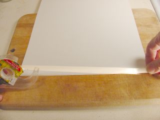
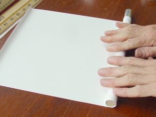
A sheet of posterboard is cut into four equal rectangles, each 11 inches wide by 14 inches long. Each rectangle, rolled the long way, will make one body tube 11 inches long. |
 |
It will resist. Persist. Get it curved all the way to the edge of the paper. A smoothly curved edge now will make a smooth, easily-rolled tube, which will not need to be rubber-banded to hold it together. Rubber bands make little ridges. If you don't pre-roll, you will have trouble at both ends. At the first end, there will be difficulty getting the first roll tight on the dowel, and the tube will not be size-conformal. At the finish, the final edge will want to pull away from the tube, and you will have to rubber-band it or something to make it lay down. Pre-rolling pre-empts these predicaments. |
 |
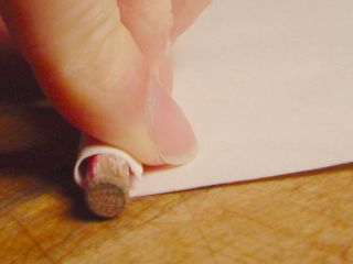
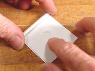
Having done all that strenuous pre-rolling, it is time to unroll one of the ends and flatten it a bit. That is so we can put double-stick tape on it. |
 |
A strip of double-stick tape is torn off just a little longer than the width of the posterboard. It is stuck to the edge, and the ends trimmed to the edge of the posterboard. |
|
|
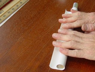
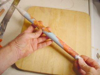
The taped edge is curled over the 3/4 inch dowel, tucked in evenly, and the first roll made. The double-stick tape secures the first turn of the tube, making the spray-glue operation much simpler. Note that the far end of the posterboard is not properly tucked. It was the best I could do and still get a photograph. Rest assured that error was corrected before I actually did the roll. |
 |
Remove the dowel from the tube to keep it from getting glued. The first turn is now secured with double-stick tape. It is protected from the adhesive spray. I guess you could mask the dowel with tape and not have to take it out. But I haven't tried that yet. |
 |
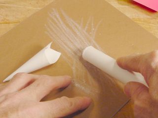
Take the paper to a spot you don't like and spray it with glue. It doesn't take much, but do strive to get an even coating. |
 |
Take it back to the flat rolling-board, re-insert the dowel, and roll it up. |
 |
 |
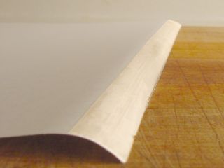
Be especially careful to get the finishing edge of the posterboard stuck down evenly and firmly. Otherwise, it will peel away and be ugly and non-aerodynamic. This is the purpose of pre-rolling that edge, so that it lays down without a struggle and sticks to the tube.
 |
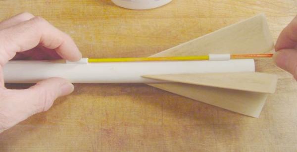
The finished tube can be worked within a few minutes. Here I am holding it to a fin-attachment guide, which is used to space out the fins at the right interval and to get them on straight. But we are getting a bit ahead here. |
Another tube we will need: Thrust ring tube
 |
A smaller tube is made in the same manner, except this one is a strip 20 inches long and wrapped around a 1/2 inch dowel. 20 inches of posterboard makes for a nice fit inside the 3/4 inch tube. It slides in with just a little resistance, so it will glue in well. This tube will be cut into short sections to make the motor thrust-ring. Such close fits can also be used to make extended airframes, either as coupling tubes to add another 3/4 inch ID tube, or by itself to make a reduced-diameter upper airframe. But beware! Long, skinny airframes make ejection more difficult, and lawn-darts are common with this model already. |
Alternative gluing method
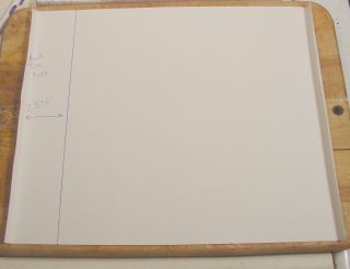 |
Just in case you don't have any double-stick tape lying around, or have a yen for doing things the old-fashioned way... You can mask the side to be rolled around the mandrel. Just draw a line 2.375 inches (2-3/8ths) from one edge. Pre-roll it and mask it with something. |
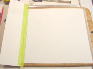 |
Here I am using a scrap of posterboard and green masking tape. Spray the remainder with Super 77, remove the mask, and roll it up! Starting with the unglued end, of course. Actually, now that I have tried it again I realize that this works very well. Forget the double stick tape. Make that two essential materials. |
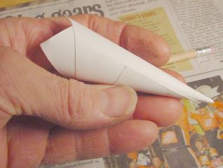
Part 3: Nose Cone
Made from a 3x5 card and 3 kinds of glue.
At work, I occasionally find myself overcommitteed. Safety committee, Parking Appeals Committee, Trauma Response Team, hiring committees, staff meetings, student organization meetings, special events projects.... So to avert death-by-boredom I carry a "meeting survival kit" with me at all times. It consists of a few index cards, a small pair of scissors, and a "stealth" bottle of Elmer's glue. With these items I can practice making nose cones while pretending to pay attention.
Even if you are not subjected to a lot of meetings, it's a good idea to practice spinning a few trial cones before getting serious.
 |
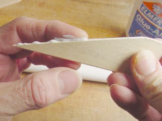
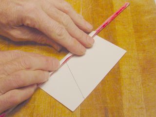
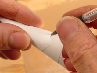
I start by making a mark in the middle of one long edge of a 3x5 index card. This is where the apex of the cone will be, and the mark reminds me of its location. To get the angle right, I make a mark on the other edge 1 inch from the side, and draw a line between the two. |
 |
|
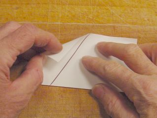
Sometimes words don't do justice, so here is a drawing. Mark the overlap line as shown. Mask the card to the left side of the line, spray the other side, and roll. This will make a nicely-proportioned cone for this airframe. |
 |
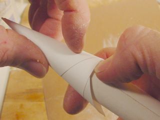
The far edge is pre-rolled on the 1/4 inch diameter dowel. This gives it a bias toward curving, both on the inside and the outside flaps. This will help make a smooth roll once the glue is applied. Inside curl will help to keep the cone round, as a straight flap will tend to distort the tube into an ovalish cross-section. Outside curl will help that flap lay flat upon gluing, rather than (un)curl up. |
 |
Top-left side is bent down to make a partial fold as shown. This is the start of the cone. |
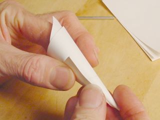 |
The cone is pre-rolled to something close to its final form. What's wrong with this picture? It was taken before I pre-rolled the edge. Note that the final flap wants to fly. It must be convinced to lay flat, that's why the pre-rolling is done. |
 |
Having done my pre-rolling duties, I may proceed. Another card is used to mask the first section of the nose cone card. Masking is not absolutely necessary, one could just spray the whole card. I did that on the first few, but Super 77 is sticky stuff, and rather annoying to have on one's fingers. Makes it hard to let things go. |
|
|
The cone is rolled again, this time with the glue. Since the final flap has been pre-rolled, it lays flat of its own accord. Be sure to check the inside and make sure the inner flap is pressed firmly against the inside of the cone. |
 |
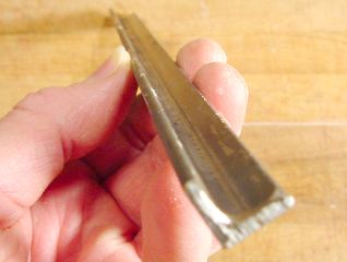
The cone will be mated to a body tube. To give it a better gluing surface, I sand the end of the tube at an angle which will match the taper of the nose cone, more or less. (Hey! a thought.... cut the body tube edge at an angle so that it rolls "stair steps up the ziggurat" with an angle that matches the cone... I haven't yet tried this, but will!) |
 |
Here is that taper I mentioned. It should provide a larger gluing surface, mating with the paper cone better than the original sharp shoulder would, right? Posterboard does not sand cleanly, but that's OK. The fuzzy stuff is of no consequence, it will be removed later. |
|
Remember that idea of cutting the posterboard at an angle? Well I did it, and here is the ziggurat. 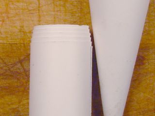 |
After sanding one to the point that it fit "right," I measured the depth of angled the edge and found it to be 1/4 inch. The board is cut so that one end is 1/4 inch wider than the other. It is 11-1/8th inch wide on the starting end, 10-7/8ths inch wide on the far end. |
 |
Less sanding is needed, and the fit is better. I'll keep this idea! |
 |
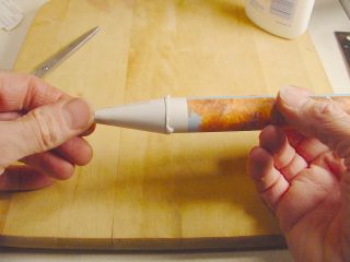
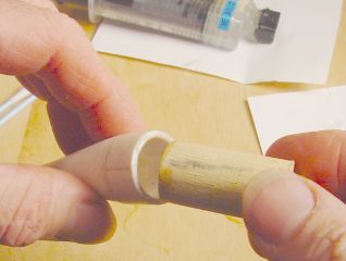
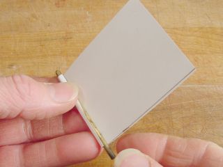
The dunce cap fits nicely on the tube, and stays put just from friction. Here I am marking the spot on the tube where this part of the cone comes.... |
 |
Marking the spot where the body tube will reach. I will trim the cone back just a little short of that mark. |
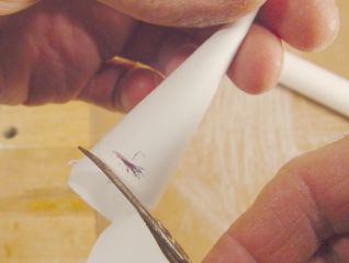 |
Cone is trimmed to within 1/4 inch of the mark. Better a little too long than too short. It's a lot easier to take more off than to add it back later. |
 |
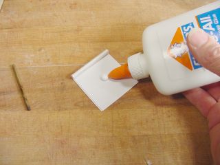
A generous glob of white glue is applied to the end of the body tube, and smeared evenly. OK, now don't get upset that we have changed body tubes here. This is show biz, and these photos were made during several different "shoots." My bad for not using a plain white tube every time, to save that much distraction and confusion. I'll tell you all about the the pretty tube later. |
 |
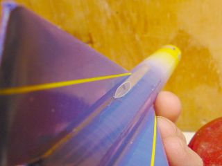
Moment of truth. The cone is pressed onto the tube. Is is straight? Must find out quickly! |
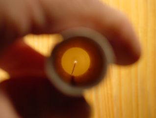 |
Apologies for the bad photo, but this shot is kinda hard to do. Sighting down the length of the tube, I noted that the center of the point (bright dot) was not perfectly centered. So I adjusted it a bit. Get that dot exactly in the middle! |
 |
Second test for straightness: While the glue is still soft, I hold the body tube loosely in my right hand and spin the assembly from the cone tip. Notice if it wobbles, and how much. Adjust until there is no perceptible wobble, at which point the cone is straight. Whew! |
 |
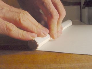
Here is perhaps a better way to get the nose straight, and doesn't require quite the motor coordination of the previous method. Lay the tube on a flat surface with the nose cone overhanging the edge, get down there with it, and roll the tube. If the nose cone is not centered, the tip will appear to bob up and down. Nudge it a little towards the middle. Roll it until the tip points down as far as it will, and move it up a bit. Roll it again. Straighten it again. When the tip rolls in a straight line, leave it alone. Let it dry. Here is a video of me doing this one. (1.3 meg .mpg file, 15 seconds of video) |
 |
There is a bit of overlap, as planned. I must confess, I had already started sanding when it occurred to me to take this picture - note abrasion on the left side. |
 |
Here is an alternative to the pre-trimming. You can glue the whole cone on, big flange and all. Then take a very sharp knife, or a good serrated knife, and trim off the excess by slicing along the body tube. This is kinda crude, but it usually works OK. |
 |
The shoulder is sanded with 150 grit or finer sandpaper to remove what remains of the skirt and make it all even. |
 |
More or less even, if a bit rough. Note that the overlap has been sanded to reduce its obtrusion. |
 |
The magic of wet-or-dry paper. Here I am using 400 grit to smooth the cone and its shoulder. This will remove the frass and make the whole thing pretty darned smooth. |
 |
But it is still porous. So I smear a layer of Elmer's glue all over the cone. This will seal and harden the surface. Let that dry for 15 minutes, and smear on another coat. That will make it smooth, glossy and much stronger. But not strong enough. It needs the third glue! We will get to that shortly. |
 |
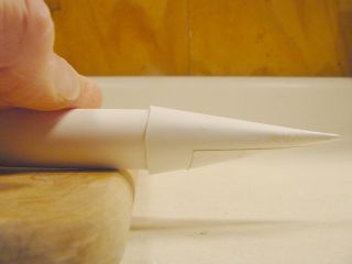
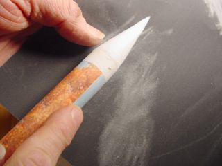
Now the nose cone is stuck firmly onto the end of the body tube. This might be OK for a pyrotechnic rocket that goes up and blows up, but that's not what this is about. Proper recovery is required, and that means the nose cone must come off to eject a parachute or streamer. So we will separate the cone from most of the tube. Remember the silvery dowel? It's the one used to roll the body tubes. I will use it here to assist in cutting off the nose cone. |
 |
The dowel is inserted into the body tube until it reaches the nose cone. This will support the far end of the body tube while it is being cut. |
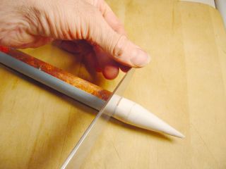 |
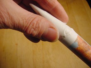
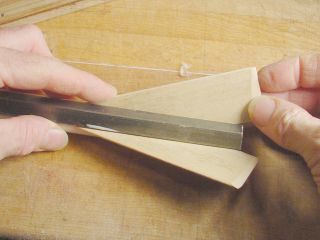
A long, sharp knife is laid on the body tube about 1/2 inch from the base of the cone, and rolled carefully back and forth to make a groove. Once a groove is established, more pressure can be applied as the knife is rolled, eventually cutting through the body tube. Click Here for a movie of me doing this with another tube (1.3 meg .mpg file, 15 seconds of uninspiring but perhaps informative video) |
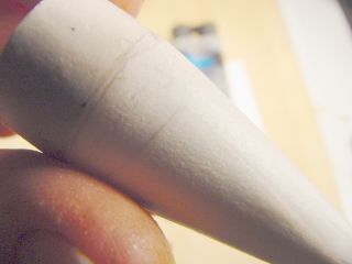 |
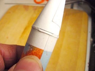
Finally, the nose cone is set free. Note that the overlapping paper has been sanded down and filled with glue-coats until it is barely visible. |
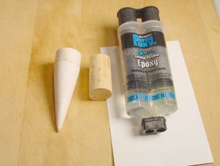 |
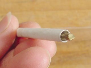
For now, it is just a thin, fragile paper cone. Compromised in places by sanding, but still intact. We will make it strong with the third glue, epoxy. A section of 3/4 inch dowel is cut to serve as a base. |
 |
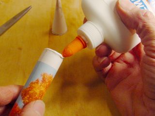
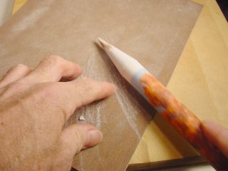
Some 5-minute epoxy is mixed up, perhaps a teaspoon. The entire interior of the paper cone is coated with this glue. I make sure that it coats the very tip of the cone to seal its small opening, and lingers in the shoulder where the short section of body tube meets the 3x5 card cone. Any glue left over is dumped in the cone and spread around the perimeter, preparing for the next step: |
 |
Dowel is inserted in the cone, with 3/4 inch protruding. The picture is deceiving - I coated the end of the dowel with epoxy before inserting it, to make sure it is glued really well. |
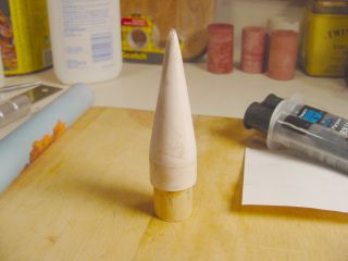 |
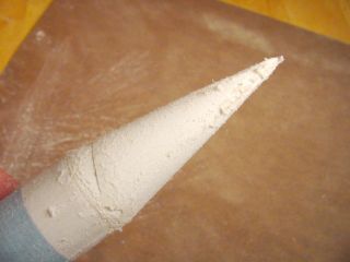
The nose cone assembly is stood upright on its base while the epoxy cures. This is so it will drip down, reinforcing the shoulder where the cone meets the tube and the paper is the thinnest. This may cause the glue at the tip to drain down, opening it up again. If that happens, give it another drop of epoxy after this first application has set. |
 |
The new nose cone assembly should fit the body tube nicely... that's where it came from! So even if the cut is uneven, or the tube is a bit out-of-round, you can rotate it back to the starting point, match the lines up, and everybody should be happy. |
|
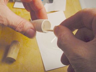
|
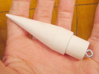
A screw-eye is added to give the shock cord something to hang onto. This is actually a different cone - note the paper base. It has a 1/2 inch wooden dowel for a core. |
 |
You can argue with the aesthetics. You can argue with the aerodynamics. But this is definitely a cost-effective procedure... once you have bought the three glues! |
Next: Finishing. You could do the usual thing with this kit - smear the fins with wood filler, let it dry, sand them, apply several coats of primer with a good sanding between coats, then give it a couple of coats of color, some striping, a finish coat, add a few decals and let it dry for a week. You could even paint pretty trees and blue sky on them.
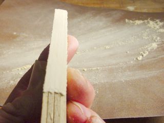
Part 4: Fins
A strip of modeling hardwood is selected. It is 1.5 inches wide by 3/32 inch thick. The best wood is maple. It is hard and strong. Next best might be basswood. Then perhaps poplar. If you can't get any of these, balsa will do. It is easy to work, but not nearly as strong.
One foot length is needed to make four fins. You don't have to use four fins, three are enough for good stability. If you are using balsa, a spare fin is a good thing to have. And if you make three rockets, you have enough leftover fins for a fourth! No extra charge.
 |
|
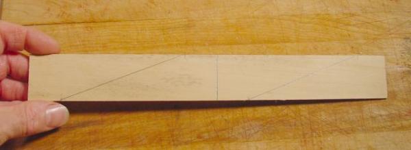
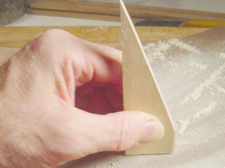
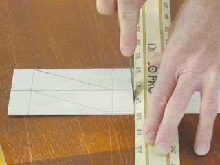
Mark the strip at the halfway point. It will be cut into into two 6-inch sections shortly. Mark a point one inch from each end, and one inch from the centerline on the opposite side as shown: |
 |
|
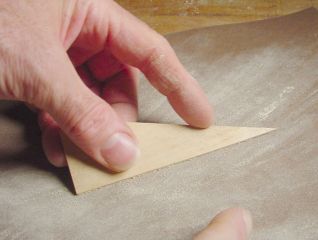
Connect the one-inch points with diagonal lines. These are the cut lines. They are also the "root edge" which will be glued to the rocket body tube. |
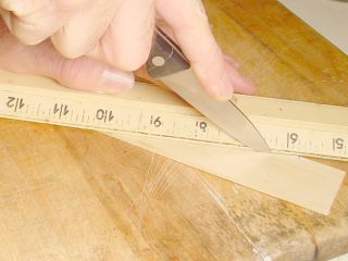 |
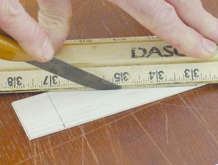
One good thing about balsa - it can be cut with a sharp knife. |
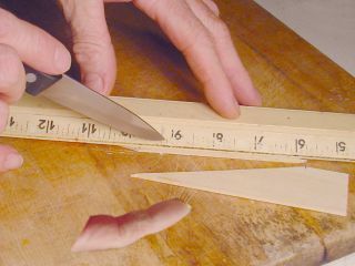 |
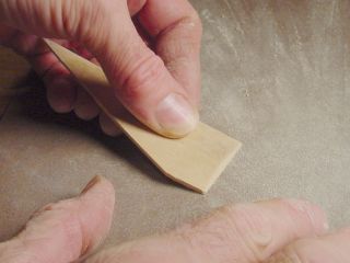
So can this basswood, but it takes several heavy strokes. Hey! Watch that knife! |
 |
 |
Isn't there a better term for what I am calling the "Adjacent Edge?" Please inform!
Fin Conformity
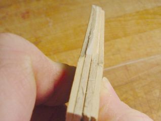 |
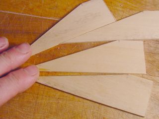
As you can see, the fins are not cut uniformly. And the root edge is not flat. That must be fixed, as the edge must
mate well with the body tube to glue well, and it must be squared with the flat so the fin will stand up straight..
The fix is a bit labor-intensive without power tools, but doable. I am the proud owner of a cheap little belt sander which does this in a jiffy. But it can be done quite well with just a sheet or two of sandpaper, a strong grip, and a few minutes of reciprocal motion. |
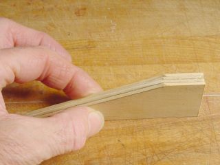 |
First, align the top edges and the 90-degree adjacent sides as closely as possible. This will minimize the amount of sanding you have to do. Pinch them together and hold them tightly so that they do not shift in relation to each other. If you have some small clamps, this might be a good time to use them. |
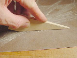 |
Lay a piece of fine sandpaper sandpaper on a flat surface, and rub the root edge of the fin group on it until they
are all flat and even. Balsa won't take long. Hardwood might take a few minutes. I'm using 150-grit here, but other sizes will work too. If the fins slip out of line, take a moment to get the top edges lined up again before sanding any more. |
 |
Here they are all sanded pretty much flush on the root edge. Might want to check and make sure they haven't slipped, though.... |
 |
Do the same thing for the trailing edges, and the adjacent edges connecting the trailing edges and the root edges. |
 |
Having been sanded as a unit, they should all now be pretty much the same size and shape. Now work on one at a time. Use the sandpaper to round all the edges except the root edge of each fin. Here I simply rub the fin against the sandpaper laying on the counter, and change the angle to make a rounded edge. Be sure to leave the root edge flat. Do not round it. The root edge needs to stay flat to maximize contact surface with the body tube when it is glued. |
 |
If you wish, the trailing edge may be tapered to a thin edge. This will make for slightly better aerodynamics.
Draw it at an angle on the sandpaper held on flat surface. |
 |
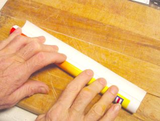
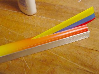
I found this steel angle iron at Home Depot, cost was only a dollar or so for 3 feet. I can't resist any thing that is both cheap and sturdy, so grabbed one. Bad idea. It had a garbled bar-code tag. Homer didn't wait around long enough for me to tell him where it came from, and apparently had to search the whole store. I waited about 20 minutes while he tried to find it. |
 |
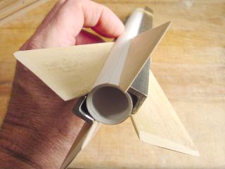
But it was worth it. This bar is just about the right size for spacing four fins around this body tube. So I cut it into 1-foot sections. Rubber-banded to the body tube, it makes for accurate fin alignment, much better than eyeballing it, or using a drawn line. |
|
|
Now that the aligner is in place, I can glue a fin. A thin bead of Elmer's is applied to the fin root. Actually, it was a thick bead, but a finger removes most of it and spreads the rest evenly. |
 |
The iron channel is used both for spacing and for fin alignment. Thus the only thing I need to worry about is
for/aft fin placement, and a pencil mark where the tip of the fin should go makes that pretty easy. Sometimes I apply candle wax to the iron to keep glue from sticking to it. It helps. |
|
|
Hey, look! I have two of these channels! Isn't that cool. As it turns out, the iron channel is much better for alignment than for placement. Since the thickness of the fins varies somewhat and so does the diameter of the body tube, a distance that is right for one airframe will be wrong for another. In this case, it's OK, it will fly stably. I could even call it an intentional "X-Fin" design. But it isn't. |
This is a very simple fin design. It is elegant in that it is very easy to cut and shape, does not waste material, and creates a very stable airframe. It is also well adapted to the "paint job cheat" technique I will describe shortly.
But other designs are certainly possible with this method. Please let me know if you come up with any really good ones!
Launch Lug. Also made from scratch.
 |
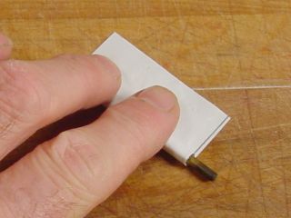
Scratch paper, that is. I cut a piece of plain copy paper 2 inches wide, 3 inches long, and pre-roll it on a short section of 1/8 inch brass rod. |
 |
A dollop of Elmer's is spread by finger.... |
 |
 |
...and the paper rolled around the rod, loosely. No doubt there is a precise way to do it, but this happens to work just fine. |
 |
|
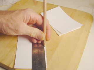
Once it has dried, a long, sharp knife is rolled over the tube which is supported by the brass rod, allowing a
nice, clean cut to be made. Two sections of lug tube are cut, each about 3/4 inch long. |
|
 |
The first is glued adjacent to a fin. This gives it good reinforcement, as well as alignment. |
 |
| After the first lug has set... 30 minutes or so... the second one can be glued on using a bamboo skewer to make sure they are aligned. Sometimes I use a rubber-band to hold the skewer down while the glue sets. In this case I just held it for a minute then gently withdrew the skewer and didn't touch it for awhile. Elmer's sets fast on porous stuff, as long as you don't use too much. |
 |
Thanks to Flint Hazpirat for suggesting the use of drinking straws for the launch lug. That would certainly save a little time. Here, such straws are usually made out of plastic, so Elmer's is not an appropriate glue. So far the hot-melt glue from my glue-gun has worked the best, as Flint also suggested.. |
Next: Nose Cone! No lathe required.
Part 5: Body Tube Covers
"Paint job" and "decals" integral with the body tube itself.
A Cheap Trick.
I went to Maine a few years ago, arriving in early October just in time for the first light snow. Everywhere I looked it was like a postcard. Sigh.
Took along a cheap little 35mm camera. Spent over $100. for film. Then over $200. for processing. Whew! Makes me appreciate the digital camera a lot more. Many of them were bad, most of the rest mediocre.
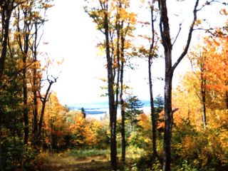 |
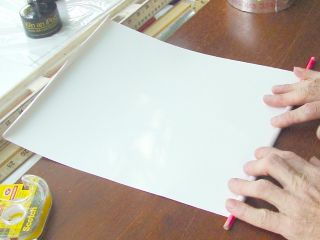
But the scenery was so good that even the mediocre shots were appealing, and on top of that, I accidentally got a
few good. Scanned the best ones, and used one of them for my desktop wallpaper at work. Someone installed a color laser printer and made the mistake of giving me access. I had to test it to see how well it would do photos, and hey! How about this Maine picture? Nice shot of some tall trees, lake, and mountains in the background. I left it laying around, as is my habit. A few months later, I was scheduled to give a presentation at conference on psychological type in education (www.capt.org) and wanted to get folks to laugh. I am willing to resort to the cheapest of tricks to get an audience on my side. |
What I wanted was a video of a homemade rocket that didn't work. Dramatically so. So I rolled a few tubes, put crude fins and a nose cone on one of them, and sprayed it with silver paint. Made a little batch of propellant, wrapped a chunk of it in aluminum foil with a firecracker at the far end, and put it in the "airframe" where the motor should be. I borrowed a camcorder, and videotaped the "launch."
During the part about development of identity in relation to career aspirations, I mentioned that: "...when I was in high school, I told all my friends that I was going to be a 'rocket scientist' when I grew up. If they had known that I would become a career counselor, I might not have survived.
"Here is one of my rockets.....
(Play video... rocket smokes for a few seconds, then explodes. Audience laughs, as hoped.)
"Well I guess it's good that I went into counseling. They say people go into helping professions because they need help...."
I rambled on and on, but nobody left until it was over. Afterward, a member of the audience asked me: "Have you seen that movie about the boys that made rockets.... forgot the name, but it's pretty good." That was the first I'd heard of October Sky. And it started me back into rocketry again. So as much as I hate to admit it, guess I'm a BAR too.
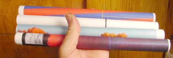
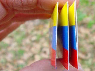
Spring cleaning came to my office, and I found the remaining tubes and the Maine photo in a heap on my desk. Hmmm. Highly distractable, especially when cleaning, I wondered: What if I wrapped the picture around a tube? Found a bottle of Elmer's and did so. Made a nicely decorated tube. I cut the picture into three strips, and rolled a section around a different tube. Stood up together, this made for a three-dimensional look, almost like real trees. I envisioned making a lamp out of them but never did. Of course.
By now, I'm sure you know where this is heading. I could quit right here and you would figure it out. Or you would say "why bother" and go do something else. But that won't stop me, nooooo! I spend most of my time talking to myself anyway, so the lack of an audience will not disuade me. In fact, an audience that is not there is hardly disuasive at all.
Thus I continue.
After building several airframes using posterboard tubes, I note that my fin spacing leaves much to be desired. I have been using 1/2 inch angle iron and 1/2 x 3/8ths inch angle aluminum to provide the correct spacing from one fin to the next. These angles are a great help in getting the fins on straight, but variations in the body tube diameter, and especially in the fin thickness, make this spacing incorrect much of the time. The rockets fly OK, but they look kinda funny.
I recalled a little helper that came with the Estes kits - a fin spacing/alignment guide. It is printed on the instructions, just a rectangle with some straight lines in it. You cut it out, wrap it around the body tube, and mark on the tube where the lines are. This provides correct spacing, and helps (somewhat) with alignment.
So perhaps I could make such guide for my body tubes? I measure a tube's diameter and figure its circumference, and divide by three. This gives me the correct spacing for three fins. I go the the computer, create an image file and draw three lines, spaced 1/3rd circumference apart. I can wrap this around the tube, mark the lines... Hey! I could just glue it on with that fancy spray glue and mount the fins directly on it! I could even use the whole length of the sheet of paper, it's gonna be wasted anyway. And it just happens to be 11 inches long.
I can print a horizontal line to show where the fin tips should reach, to help with fore/aft placement.
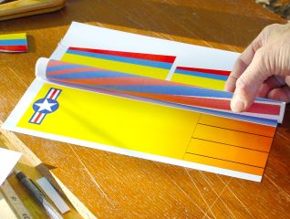
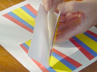
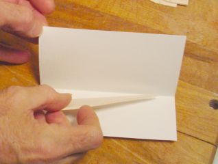
So I print out two such guides on one sheet, and cut one of them off, a strip wide enough to go around the tube and then some, sprayed it with glue, and wrapped it around a tube....
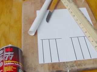 |
It worked very nicely! The fins went on straight, thanks to the angle-aluminum guide. They were evenly spaced thanks to the longitudinal lines, and fore/aft placement good enough that it would stand up on its own, thanks to the end-mark. |
 |
 |
|
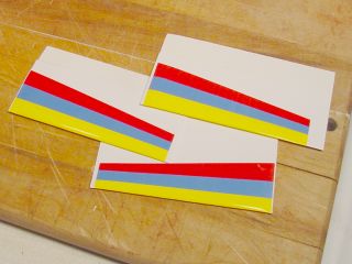
So I went kinda wild. And soon realized that it is really easy to do a bad job of this. Here are a few examples: |
Note that they are kinda dusky and drab looking. These are printed on plain paper. It occurs to me that I have some expensive glossy photo paper here somewhere..... (sound of drawers opening, cabinets rattling, things falling to the floor) Hey! I found it! What luck.
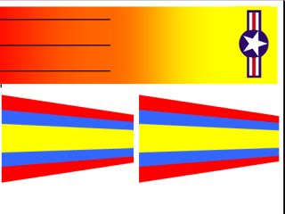 Click Here to open the Word version of this graphic |
But if I am going to use dollar-a-sheet paper, I want a better design. So I went online and found Kurt Schachner's
collection of decal designs for historic Estes and Centuri models,
from which this star-n-bar insignia was obtained. I used Word to make the gradient and the fin covers. Yeah, why not cover the fins too, save a lot of sanding, painting, etc. Besides, the paper serves to reinforce the wood, so I can use 3/32 inch balsa and it might not break right away. Here is a Word doc with 3 fin covers on it. Guess I should work up a design that gets 3 fins plus tube cover on one sheet. I have a variation in yellow and blue. |
 |
The wrap should be about 3 inches wide. The body tubes average about 0.9 inches, so the circumference would be 2.82
inches. Divide that by 3 and you get 0.94 inches between fins. Since the paper thickness will add a bit, I am using a
fin spacing of 1 inch here, and it is about right. Fine tuning may be helpful, but this is good enough for a start.
Here I am sizing up an ugly tube to see if it can be recovered. Decided against it, thinking the extra coating of paper might make the new alignment lines incorrect. I made a new tube instead. |
|
|
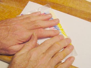
Sprayed the wrap with Super 77 and rolled it on. This is easy! But I forgot something.... |
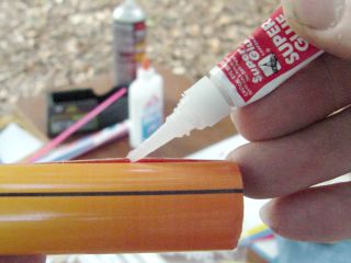 |
There were a couple of gaps in the final edge. I had failed to pre-roll the edge. That was not necessary with the
plain paper, but this photo paper is much thicker and stiffer. Elmer's didn't work, it just yawned wide open again. So I tried a little super-glue and guess what! It works really well. |
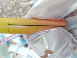 |
Note that I'm holding the edge down with a thick plastic bag. Getting CA'd to something is funny when it happens to someone else.... Super glue doesn't seem to stick to polyethylene baggies at all. |
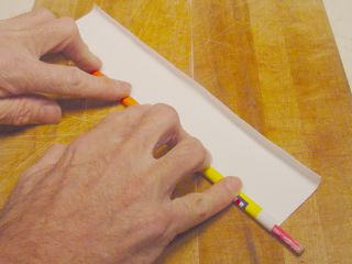 |
So here is another wrapper. I'm doing the pre-roll thing this time. Glued it on, and it works great. No loose edges. |
 |
Fin Covers
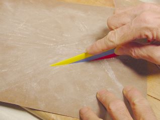
You might have noticed the gaily-colored trapezoids on the printout. Those are fin covers. We need some fins to cover.
 |
Here I'm cutting fins from 3/32 inch thick balsa. The strip is 3 inches wide, so I split it in half. Thus each 6-inch section makes 4 fins. The leading and trailing edges of these fins will be rounded or tapered with sandpaper, as illustrated on the Fins page. |
 |
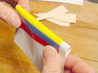 |
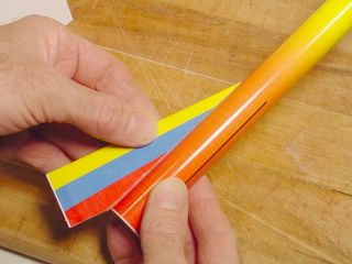
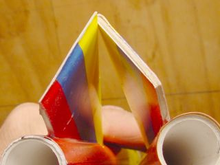
A colorful trapezoid is cut out, with a lot of extra paper around the edges. It is folded directly down the middle
so that the colored stripes are symmetrical and even on both sides. This is a test-fitting to make sure it goes in OK. It does. |
 |
|
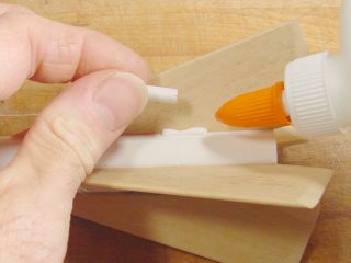
|
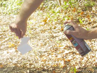
Good way to get stickyfingers. But when I set the paper down, the spray blows it over! Guess I could use a clothespin or something. If you want the bond to be extra strong, spray the balsa with glue too. Fin is inserted into glued paper... |
 |
 |
...folded in a Ziploc bag, and pressed firmly. The bag keeps my sticky fingers from adhering to the paper. Don't
want to leave any fingerprints, do we? This procedure creates a fin packet, a colorful fold of heavy, glossy, pretty paper with a balsa fin somewhere inside it. |
 |
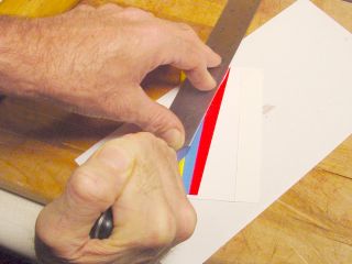 |
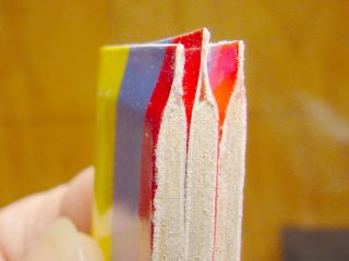
By pressing at the edges with a fingernail, I find where the balsa begins and lay a non-skid ruler along that line.
Sharp knife is used to cut away the excess paper. I notice that it is so easy to cut through the balsa like this that I don't even notice when it happens. Ruined a fin that way, but it suggests another technique, to glue paper to balsa, then cut it out. |
 |
Root edge of each fin is sanded to remove excess paper and make the edge flat and true again. The remaining paper
flares out a little. I leave this frilly edge on believing that the tiny tendrils will make for a better glue joint. |
|
|
The aluminum bracket is rubber-banded to the body tube and aligned with one of the fin index markers. A dollop of Elmer's is spread along the root edge, and the fin pressed into place. After about 30 seconds, the aluminum guide is moved to one side so that the fin does not get stuck to it. The fin is allowed to dry for a few minutes before adding the next. |
 |
Falling Fin Syndrome
When I first glued these fins to the body tube, they kept falling off! Apparently, the glossy photo paper does not absorb Elmer's Glue as readily as plain paper. I feared I would have to find a different glue. But I left one sitting for 15 minutes, came back and tried to pull it off. It did not come off easily, it was stuck on pretty well. So I left it to dry overnight, and the resulting bond was quite strong. So Elmer's is fine. One must take a little more care in the beginning, and have a little patience in the middle for a good result at the end.
Trailing Edge Surprise
 |
Here is a bonus. I hadn't planned on this and so did not do it very well. Instead of trimming the paper right up to the balsa, I left 1/4 inch or so and presed the edges together. It made a nicely feathered trailing edge. I'll try to do it better next time. |
 |
But compared to the first of these I made with a very square end, the paper taper is grand. The edges can be trimmed with scissors so they are all even. |
 |
Here is that better job I promised. Note that the fin itself is inside a covering of heavy polyethylene (a Ziploc freezer bag) to protect the finish. |
 |
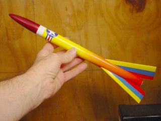
It worked! The two on the left were done with the clamps, the one on the right wasn't. It can be fixed with a touch
of super glue, but I prefer to do a good job to start with. I like clamps. Clamps are good. |
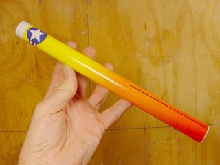
 |
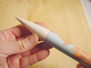
The left model uses the paper nose cone illustrated on that page. It looks kinda awkward. It needs a paint job. The red nose cone is one I turned on a wood lathe. |
 |
Top Coat
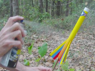 |
This printed photo paper stays kind of "sticky" for a long time. So after drying, I give it a couple of
coats of clear "top coat" lacquer. This makes it much less sticky and more water resistant. I unserstand that there are special fixative sprays for inkjet photo-paper. Perhaps I should get some. But this Plasticoat lacquer works petty well. |
So far I have this one gaudy design. More a test of concept than anything. How about some of you rocket artists designing better ones and sending them to me? I would be delighted to post any that you submit, with your permission, of course.
A good starting point might be Ye Olde Rocket Shoppe which offers a nice collection of decal designs from historic Estes and Centuri kits, as well as plans for many olde and newe rocket designs.
Deepest thanks to Kurt Schachner for collecting these the decal set from which I obtained the star-and-bar, and to Scott Hansen for putting them on the web.
Next: Finishing up!
Part 6: Finalizing
Thrust Ring, Recovery Streamer, Motor Retention, Launch!
Thrust ring and shock cord
 |
Remember that second tube I made for a thrust ring way back when? It was 20 inches of posterboard rolled on a 1/2
inch dowel. Well this isn't it. I changed my mind. The reason is that we need a good way to mount the shock cord. The way it was done in the RS101 class may have contributed to the large number of ejection failures. I think this method will work OK. The new tube is made from 14 inches of posterboard just like the airframe. But instead of being rolled on a 3/4 inch dowel, it is rolled on a 1/2 inch rod. That makes it a loose fit in the airframe tube, and that is a good thing. I cut off an inch, and tie one end of an 18 inch length of shock-cord elastic around it. |
 |
This is plain old underwear-type elastic, 1/4 inch wide. It is available from any fabric store, craft shop, sewing
department of a department store, or I guess you could cut some from the missus' undies, but I don't recommend it. The
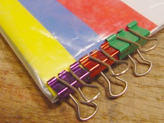
social repercussions could be dire. After tying the elastic, the tube is wrapped with another strip of posterboard, just enough to go around the tube one time plus a little overlap. I used green posterboard for the final wrap so you could see it. It was sprayed with Super 77 before wrapping, and is secured with rubber bands while the glue sets. |
 |
This should provide a smooth fit into the airframe tube, a solid bulkhead against which the motor will thrust, and
a secure mounting for the shock cord. Too bad the shock cord is so close to the motor - it might get burned a bit upon
ejection. Oh well. The shock cord elastic is run through the body tube, and is dangling out the nose end of the airframe. In a moment, I will put a big glob of Elmer's in the airframe, and use a spent motor casing to push the green thingy up to the right spot. |
 |
Did you catch that? I had to move quickly, and did not get a photo. But I did what I said, squirting a globular
ring of Elmer's around the inside of the airframe tube at the fin end. Then I inserted the thrust ring tube, and used a spent Estes motor casing to push the tube forward about three inches. This leaves the nozzle of the Estes casing about 1/2 inch inside the tube. That is good. That's where we want it. But not for long. I find a stick, and push out the motor casing before the Elmer's has time to glue it in permanently, and make my potential rocket into a non-flying shelf ornament. |
 |
The thrust head has been pushed into place and the glue is allowed to set. Should be firm by now, so I'll launch it shortly. |
Nose cone and streamer attachment
 |
Nose cone is tied to the shock cord, and a gaudy streamer added. My field is kinda small - models using parachutes sometimes don't come back. The streamer is simply surveyor's ribbon. It's primary virtues are that it is cheap and highly visible. |
 |
Here is an error to avoid: When inserting the nose cone, make sure the free end of the shock cord does not get
pinched between the nose cone and the body tube. There were several ejection failures in my Rocket Science 101 class, and I think this is one of the reasons. The other is that we were using the traditional method of motor retention, wrapping the motor with masking tape until it was a tight fit. Not tight enough in some cases, so here is a better way:
|
Positive Motor Retention
One of the problems with my original "kit" was motor ejection. When the motor fired its ejection charge at apogee, it was often the motor that was ejected, in spite of massive wads of masking tape trying to keep it in. When the motor ejects, the nose cone often doesn't, resulting in a lawn dart. We had quite a few of those on the RS101 launch, so here I am trying to do better.
 |
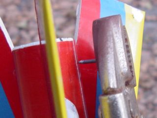
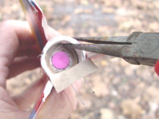
Two small holes will be burned in the airframe tubing, just past the motor. A short section of stiff wire will be
inserted, to prevent the motor from moving backwards upon ejection. After the glue has had a few minutes to dry, I put the casing back in and measure the depth from the end of the airframe. Using my rule of thumbs to mark the depth on the outside of the airframe, I will burn a hole here soon. |
 |
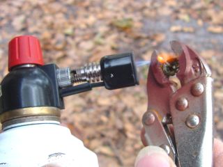 |
OK, so I'm not really burning a hole in the second photo. Mostly, I'm taking a picture! This little tack loses heat very quickly, so if I'm distracted (which is likely!) it will cool down before I get around to using it. But I did it again after putting down the camera, and made a hole at the spot indicated. Then I made another one on the other side of the closest fin. |
 |
|
|
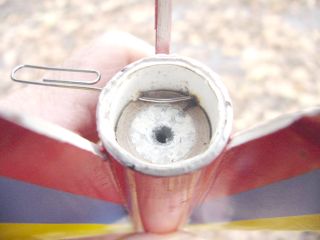
Here's why. I'm going to use a piece of this paper clip for motor retention. |
 |
Spent casing is removed and replaced it with a live Estes motor. Paper clip is clipped, and I am bending the ends so it can't wiggle out. Since the motor is recessed, it's a lot easier to install the ignitor before putting it in the airframe. |
Test Launch
|
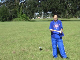
Here it is on the launch pad, ready to go. Click here to see the launch (2 meg .wmv file, 27 seconds of highly compressed video) Summary: Successful launch, good recovery. It will fly again. |
Other Tests
This model was pretty well tested in the Rocket Science 101 class launch, where 10 of these models were flown a total of 30 times, using Estes A, B, and C motors. All fights were stable. Some did not eject as planned, but survived the lawn dart recovery with minimal damage. Wooden nose cones were used - I had not developed the paper verison at that point. It is doubtful that paper cones would have held up as well, unless perhaps they were filled with epoxy or some other solid substance.
Please let me know what you think of this project and the site describing it.
Praise and adulation are welcomed, but suggestions and criticisms are equally valued.
And if you come up with any good "wrappers," please send them to me!
 |
 |