Scratch Temporary Insanity Original Design / Scratch Built
Scratch - Temporary Insanity {Scratch}
Contributed by Cliff Oliver
| Manufacturer: | Scratch |
Note: This is a slightly edited version of all the information that Cliff has produced for his Level 3 project. Download his MS-WORD document here (29M) to see a few more pictures and details.
Introduction
 Temporary Insanity is a single staged three finned rocket. The design is an upscale loosely based on
the Aerotech Mustang mid-power model rocket. The differences are the shape of the nose cone and number of fins. My
project has three clipped delta fins.
Temporary Insanity is a single staged three finned rocket. The design is an upscale loosely based on
the Aerotech Mustang mid-power model rocket. The differences are the shape of the nose cone and number of fins. My
project has three clipped delta fins.
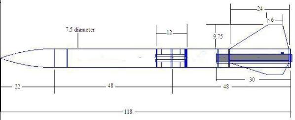
The basic dimensions are:
- Length: 9 feet 10 inches
- Diameter: 7.51 inches
- Launch weight: 45 pounds
- 98MM motor mount / 75MM adaptor
The certification flight will be on an Animal Motor Works M1850GG motor. According to simulations performed with Rocksim 8 software, using this motor will yield an altitude of approximately 6000 feet AGL.
The design if this rocket uses two altimeter bay tubes. They are positioned parallel to the airframe and to each
other on each side of the inside of the airframe. Static port holes are drilled thru the airframe and the altimeter bay
tubes. The power and shunting switched are mounted on the altimeter sled and are accessible thru these port holes. The
main ejection charge holders are 12 inches long and extend from the aft altimeter bulkhead to the main payload section.
All electronics, associated wiring, switches and ejection charge holders are mounted on sleds which are attached to a
removable cover plate. This facilitates easy accessibility to the electronics and ejection charges.
Scale Drawings
Scale drawing showing major components and their dimensions.
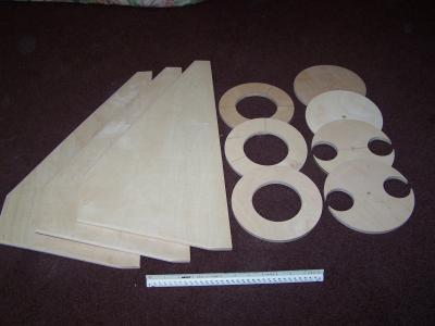
Construction
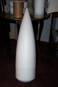
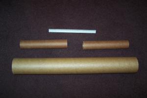
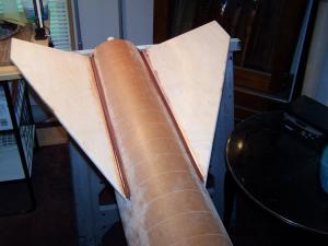
Construction began by gathering parts. Below are the fins made of 3/8 inch plywood, ½ inch plywood centering rings, three ½ inch and one ¼ inch bulkheads. The nose is from LOC/Precision. It is 7.5 inches in diameter and made of plastic.
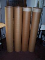
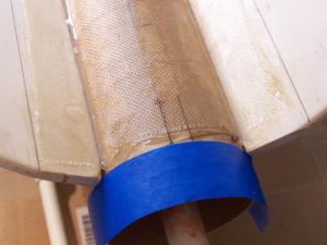
Next are the two 54MM tubes for the altimeter bays, 98MM motor tube, phenolic body tubes, and phenolic tube liners. The airframe tubes are shown with the first layer of card board peeled from the forward ends in preparation for reinforcement with Kevlar tape.
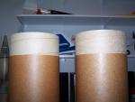
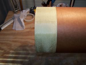
Three inch Kevlar tape reinforces the forward ends of both body tubes. This step will strengthen the tube ends to prevent a zipper.
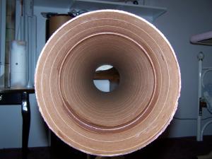
The entire airframe was reinforced with phenolic liners. The liners were secured in place with marine grade epoxy.
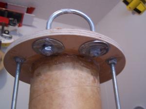
The booster section attachment points for the recovery harness are 5/16 inch U-bolts. Fender washers on the underside of the center ring provide greater support.
 Three 8-32 T-nuts were installed in the aft centering ring to use as motor retention. A Slimline
retainer/adapter will be installed in a later step. Screws will engage the outer flange of the retainer to provide
greater security for the retention system.
Three 8-32 T-nuts were installed in the aft centering ring to use as motor retention. A Slimline
retainer/adapter will be installed in a later step. Screws will engage the outer flange of the retainer to provide
greater security for the retention system.
The fins were attached to the motor mount with marine grade epoxy. Colloidal silica was added to the epoxy for strength.
A layer of 6 ounce fiberglass was laid between each fin and reinforces the fin tab to motor mount
joint.
The aft centering ring was not installed until the fin can was secured in the aft body tube and the interior fin fillets were completed.
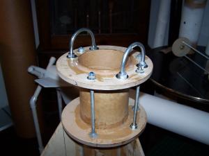
Here, the aft centering ring is installed. Epoxy thickened with colloidal silica was placed on the outside of the motor mount and the inside of the body tube. Then the centering ring was installed. A fillet was added t the body tube centering ring joint. A Slimline motor retainer will be added during a later step.
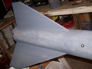
 Exterior fin fillets were added using epoxy and colloidal silica for the first layer. The second layer is
epoxy and phenolic micro balloons.
Exterior fin fillets were added using epoxy and colloidal silica for the first layer. The second layer is
epoxy and phenolic micro balloons.
A 1/8 inch hole is drilled into the booster section to equalize interior airframe pressure to ambient pressure during flight to prevent premature separation of the sections.
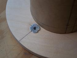
Here, I am installing a threaded brass insert into the lower centering ring for the lower rail button. I drilled the holes into the rings large enough for the insert. Then applied thickened epoxy to the hole and screwed the insert in until it is flush with the airframe. The upper rail button is attached to the forward centering ring using the same method. The buttons are Series 1500 Delrin from Railbuttons.com.
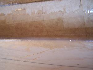
The payload section is also on the bench with the spiral filler drying. The large white section at the bottom is actually the top of the section where the Kevlar tape has been used for reinforcement.
1500 Series Delrin rail buttons are installed into the brass inserts for guidance.
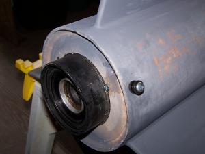
A Slimline motor retainer was installed using JB Weld and three 8-32 screws and T-nuts. A Slimline 98/75mm motor adaptor is used to mount the AM M1850GG motor.
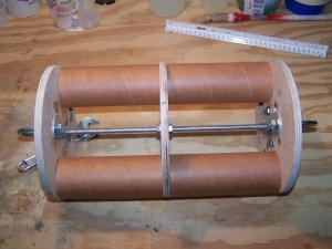
The altimeter bay consists of three ½ inch plywood bulkheads. Two of them have been cut to accept two 54MM tubes that house the avionics with associated switches and wiring and two 24MM holes for the conduit tubes. A 5/16 inch threaded rod is attached to all three bulkheads for reinforcement
Two 24MM tubes are used to allow easy passage of the main ejection charge holders to the forward payload section. The two ¼-20 bolts secure the cover plate to the assembly.
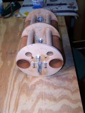
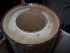
Here the altimeter bays are installed into the forward payload section.
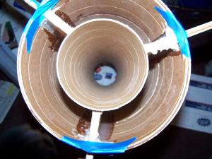
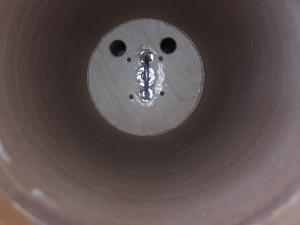
This is the view of the inside of the payload section. The two large holes are where the ejection charge holder/conduits come into the bay. The four smaller holes have been filled with epoxy
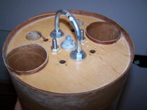
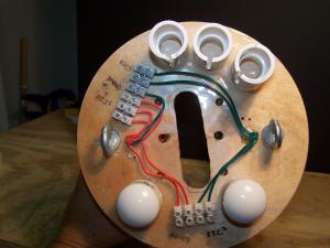
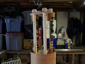
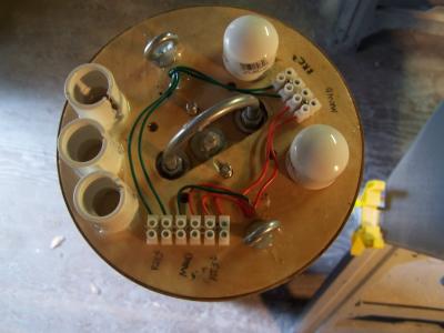
This is the cover plate for the altimeter section. The main ejection charge holders/conduit made of PVC tubing and altimeter mount sleds are attached to this. Three apogee ejection charge holders are made from PVC couplers cut to facilitate ejection charges. The wiring blocks are labeled to ensure proper connection of the igniter leads. The PVC caps cover the ends of the main ejection charge holder/conduit. They are slotted on the side to allow the igniter leads to pass. A small screw will secure them during flight. The two eye bolts are pull handles to aid in removing the assembly from the rocket.
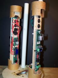
Attached to the sleds is a Perfectflite MAWD, MT3G timer and a Missile Works RRC2 altimeter. Each of the three devices is equipped with its own power supply, power switch, shunting switches and ejection charges. Each ejection charge has its own shunting switch.
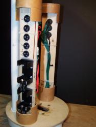
This entire assembly slides into the 54MM and 24MM tubes in the altimeter section. Coupler tubing located at both ends of the sleds seal the altimeter bay tubes. The PVC tubes are ejection charge holders and conduits for the igniter leads.
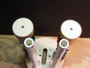
Here the cover plate is installed into the altimeter bay. Wing nuts (not shown here) are used to secure the plate to the rocket.
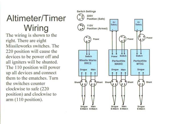
Static portholes are drilled through the airframe and altimeter bay tubes on both sides of the rocket. This allows access to the power and shunting switches mounted on the altimeter sleds using a small flat blade screw driver.
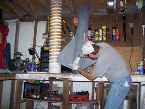
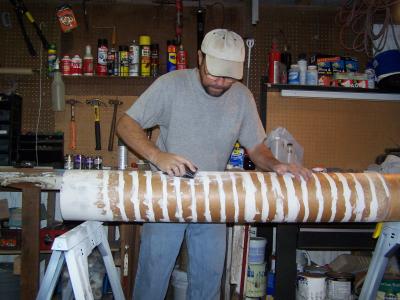
Sanding
Here, I am sanding the filler on the payload section.
A 3/8 x 4 inch eye bolt is secured in the nose cone bulkhead by a nut and washer on the exterior. On the interior there is a fender washer and nut. A 24 inch length of threaded rod is attached to the remaining eye bolt threads with a threaded coupler. The forward end of the rod extends to the tip and is embedded in a mixture of epoxy and BB’s. This mixture is used for nose weight to ensure the proper stability.
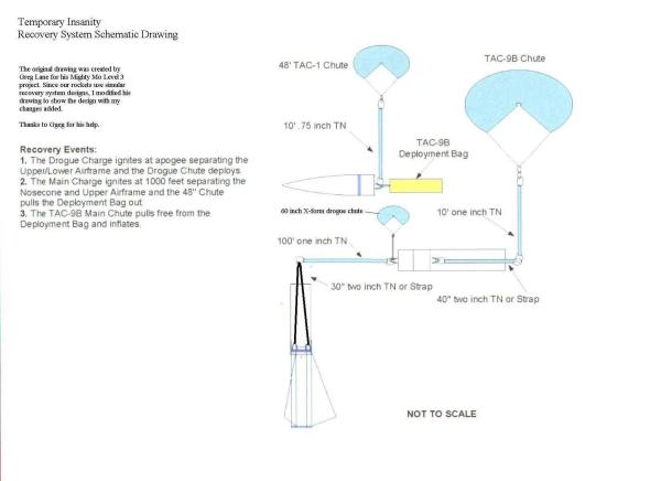
Recovery System
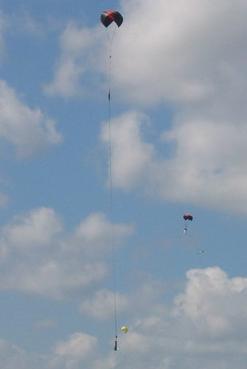 A 60 inch x-form drogue chute will be deployed at apogee by black powder ejection charges controlled by a
Perfectflite MAWD and a Missile Works RRC2 altimeter. These altimeters are backed by a Perfectflite MT3G timer set to
fire approximately 22 seconds after launch. Each device fires its own charge. The drogue will slow the rocket’s
descent to approximately 57 feet per second and orient the payload section to prevent fly thru of the main
parachute upon its deployment.
A 60 inch x-form drogue chute will be deployed at apogee by black powder ejection charges controlled by a
Perfectflite MAWD and a Missile Works RRC2 altimeter. These altimeters are backed by a Perfectflite MT3G timer set to
fire approximately 22 seconds after launch. Each device fires its own charge. The drogue will slow the rocket’s
descent to approximately 57 feet per second and orient the payload section to prevent fly thru of the main
parachute upon its deployment.
At approximately 1000 feet AGL, the main 98 inch diameter TAC9-B parachute will be deployed by black powder ejection charges controlled by a Perfectflite MAWD and a Missile Works RRC2 altimeter. A deployment bag will be used to ensure proper deployment of the main chute. A 48 inch diameter parachute which is attached to the nose cone will pull the bag off of the main chute. The nose cone and deployment bag will descend separately at approximately 17 feet per second. The main parachute will land the rocket at approximately 15 feet per second.
The drogue parachute compartment is located in the booster section and the main parachute compartment is located in the payload section of the rocket. Masking tape will be used to adjust the fit of the coupler and nose cone to the airframe. Three 2-56 nylon screws will be used as shear pins at both separation points to prevent premature separation and deployment of the recovery systems.
A harness made from 4 feet of 2 inch nylon webbing is attached to the two U-bolts installed into the booster section upper centering ring. Attached this way, the webbing forms a "V" shape. The shock cord, which is 100 feet of 1 inch tubular Kevlar, is attached to this point. The drogue is a 36 inch diameter nylon chute from LOC/Precision. Quick links are used to attach the harness to the booster and payload sections as well as the drogue. Swivels are also used where twisting of the harness is expected. A Nomex chute protector along with cellulose insulation (dog barf) is used to protect the drogue recovery components.
6 feet of 2 inch nylon webbing is attached to the U-bolt installed into the forward bulkhead of the altimeter bay. The aft end of the webbing is covered by a Nomex sleeve to protect it from ejection charge heat. A Giant leap TAC9-C parachute is attached to one end of 100 feet of 1 inch tubular Kevlar shock cord. The 2 inch nylon webbing attached to the other end. The main chute is incased in a deployment bag. This bag is attached to the nose cone and a 60 inch diameter parachute via a harness. Upon deployment of the main recovery system the 60 inch chute will inflate and pull the bag from the main chute. The nose cone and deployment bag will descend separately on the 60 inch chute. A Nomex chute protector and cellulose insulation will protect the recovery components from ejection charge heat.
Stability Evaluation
The rocket’s stability was determined by simulations using Rocksim v.8. At liftoff the minimum Aft CG at 77.3 inches and the CP at 89.2 inches from the nose tip. This gives the rocket a stability margin of 1.55 calibers. According to Rocksim flight simulations, the margin should not drop below 1.55 during the flight.
Expected Performance/Flight Profile
This data was generated by Rocksim 8 software. Several sims were performed for flights on a AMW1850GG motor. A simulation for different wind/weather conditions was run. One simulates a launch with light winds of 3 to 7 mph. Another simulates slightly breezy wind of 8 to 14 mph and for winds of 15 to 25 mph.
General flight profile is as follows.
- Max velocity: 869ft/s
- Time to burn out: 3.2 sec
- Time to apogee: 20.6 sec
- Altitude at apogee: ~7000 ft
- Velocity at drogue deployment: 43 ft/s
- Descent velocity under drogue: 50 ft/s
- Altitude at main parachute deployment: 1000 ft Descent velocity under main parachute: 15 ft/s
- Total time of flight: 164 sec
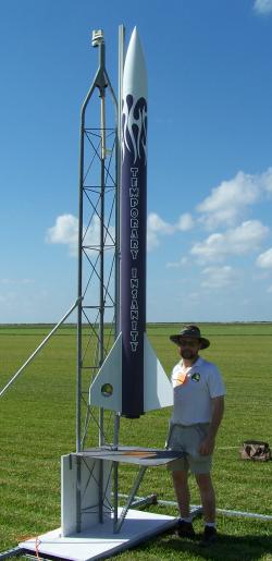
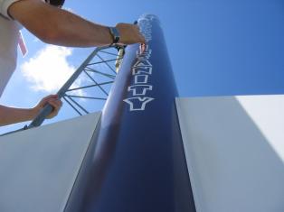
The rocket was finished using Krylon white and gray primers. The color coat is Krylon Glossy White and Gloss Purple. I have always liked flame patterns. So, I contacted Dave Rose at Graphix and Stuff and told what I had in mind. He worked up an image of what the rocket would look like with his proposed vinyl decals. It was perfect! He sent a set of white letters and a white tribal flame "Rocket Wrapz". One tip I’ll pass along here. Get some more hands to help apply the wrap decal. I did not and although it went on kind of straight. There are still some wrinkles that I covered and some that disappear with a little distance. Don’t get me wrong. The decals are top notch. My application was at fault.
 SUCCESSFUL LEVEL 3 FLIGHT!
February 16, 2008 Florida Winder Nationals
Rocket - Scratch Build Temporty Insanity
Weight - 45lbs
Loaded Motor - Animal Works M1850GG
Altitude 5000 Feet
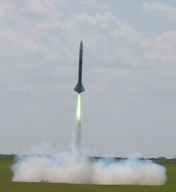
I launched Temporary Insanity for my NAR L3 certification at the 2008 Florida Winter Nationals Feb. 16, 2008. Everything went flawlessly. Well, except for the igniter that got spit out the first attempt to launch it. After another one was placed in the motor, hooked up and the countdown reached zero, the rocket flew to 5000 feet and returned to within a few hundred yards of the pad. No damage and my signed certification application was in the mail the following work day!
Many thanks to fellow SEARS club members John Hansel and Greg Lane for their help and loaning me the recovery harness, chutes and motor casing. They were instrumental in my success. Also, thanks to Rick Boyette of Florida Space modeler/Tripoli West Palm for his help and acting as my L3CC.
 |
 |