Scratch The Gension Original Design / Scratch Built
Scratch - The Gension {Scratch}
Contributed by Scott Turnbull
| Manufacturer: | Scratch |
Building The Gension (rhymes with tension)
Overview:
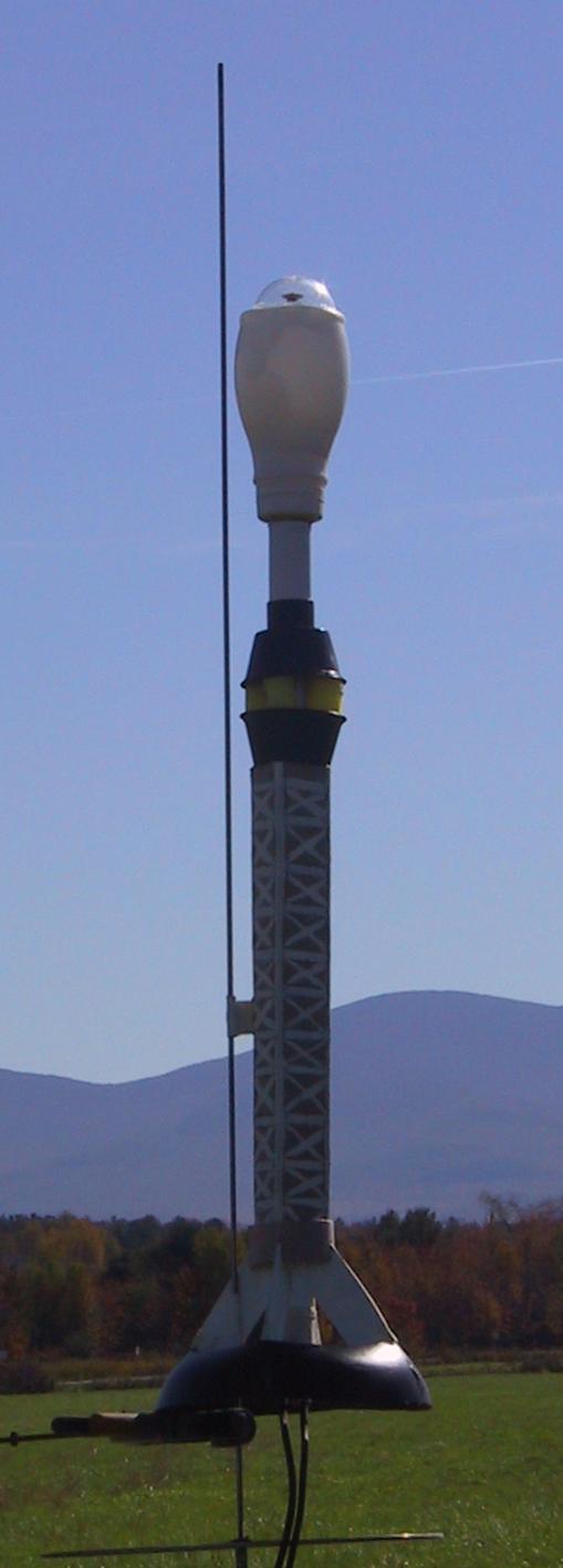
This article describes the construction of The Gension, a scale model of an Ion Powered Generation Starship. It features a 24mm motor mount, ring fin, squared off airframe, and a bulbous nosecone tipped with a clear plastic dome.
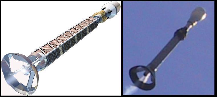
The Gension is a hypothetical interstellar ship carrying a community of 500 travelers on their multi-generation voyage. The ion drive is constantly accelerating the ship at 1/6 Earth Standard Gravity, providing the community with a feeling of solid ground under their feet. A strong electromagnetic field generated between the upper and lower rings of the drive structure accelerates the ions. The drive generates a stream of energetic particles, which are hazardous to the travelers. To protect the inhabitants, the drive is kept far behind the residential section by an extended framework of girders. Extensive radiation hardened inhabitable space is available within the forward section. At the very top of the ship is an open green space, under a transparent dome. This allows the inhabitants to enjoy wide-open spaces with an unparalleled, perpetually star spangled sky. Several generations will be born, start their families, grow old, and pass on before The Gension reaches its destination at a distant star system.
Bill of Materials:
The following materials are needed to construct The Gension.
- 18" 24mm motor mount
- paper towel tube (for squared off superstructure)
- thin plywood from Clementine fruit crate (for flat fins)
- heat resistant plastic microwave dinner bowl (for ring fin)
- 2 black plastic condiment cups (for gas cylinder mounting)
- scrap of foam swim noodle (to fashion gas cylinders)
- single serving plastic milk bottle (for bulbous nosecone)
- plastic dome from gumball machine
- fishing leader and shock cord
- used 24mm motor casing
- short section of BT70 tube for ring above fins
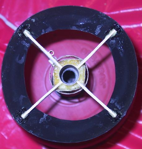
Fin Assembly:
 The fin ring is made from a heat resistant
black plastic bowl that originally contained a microwaveable dinner entry.
Using a razor knife, slice off the bowl rim, and the bottom, leaving the side
of the bowl for use as the ring fin. Placing a 24mm motor casing in the center
of the ring, fashion cardboard templates for the four fins. The specific mount
angle will be determined by the size of the ring, and how far below the fin
root you want the ring to mount. The fin should initially reach all the way to
the bottom edge of the ring, but that will be adjusted in a subsequent step.
The fin ring is made from a heat resistant
black plastic bowl that originally contained a microwaveable dinner entry.
Using a razor knife, slice off the bowl rim, and the bottom, leaving the side
of the bowl for use as the ring fin. Placing a 24mm motor casing in the center
of the ring, fashion cardboard templates for the four fins. The specific mount
angle will be determined by the size of the ring, and how far below the fin
root you want the ring to mount. The fin should initially reach all the way to
the bottom edge of the ring, but that will be adjusted in a subsequent step.
Using your preferred fin stock make four identical fins. My choice was to use thin, 3 layer plywood from a Clementine fruit crate. Surface mount these four fins equally spaced approximately one inch up from the bottom end of the 24mm motor tube. I used yellow glue for attachment and fillets.
Slide the ring down over the motor tube until it rests evenly on the leading edges of the four fins. Mark the fins where the upper edge of the ring rests against them. Depending upon your choice of fin and ring material, you may be able to simply glue the ring on the slanted edge of the fins.
After one hard knock, I found that a more structural interlock was needed to keep the slick plastic ring firmly attached. To achieve this interlock, notch each fin a short distance below where the ring originally rested on the fins. The ring can then be pushed down until it snaps into the fin notches. To further interlock the fins, leave a tab at the fin tip that extends through slots cut into the ring. I used a Dremel cutting wheel to notch the fins and cut slots in the ring. A Dremel sanding drum was used to grind the fin tips flush with the surface of the ring.
Paint the lower body tube and fins white before attaching the fin ring.
When the tabs are done right, glue is almost an afterthought. I hedged my bets and used Gorilla Glue to bond the fins to the ring. A black marker pen can be used to blend the fin tabs with the large fin ring.
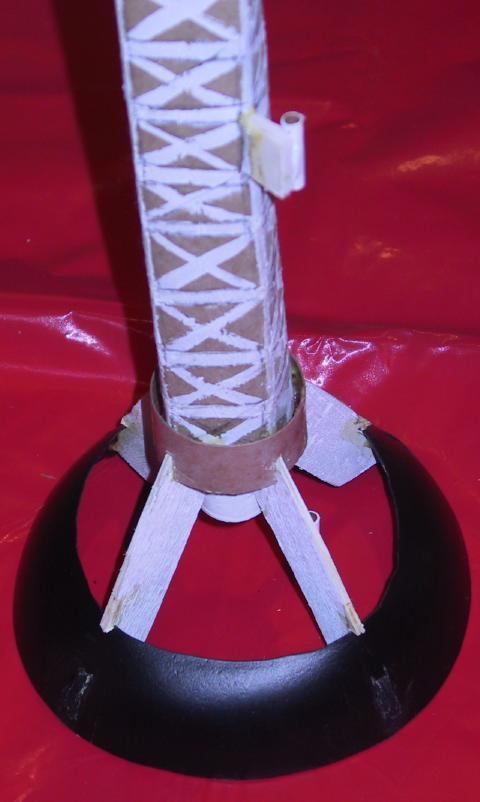
Airframe Assembly:
A cardboard paper towel tube is used to fashion the desired square framework airframe. Start by crushing it flat. Reshape it to an approximate cylinder, rotate it a quarter turn, and flatten it again to form four creases that run the full length of the tube. Using those four creases, form the tube into a square superstructure.
Mark the dimensions of the square superstructure cross section on a scrap of leftover fin material. Cut a hole centered in the marked square to fit over the 24mm body tube. Cut out the square bulkhead and glue it inside the top of the square superstructure. A simple method to give the impression of the framework on the superstructure is to outline it with pencil, then paint it with white acrylic. Use more pencil to create faux shadows that imply depth of structure for the framework.
Slide the open end of the decorated superstructure down over the motor mount tube until a corner rests at each leading fin edge. Slot the bottom of each superstructure corner so that it slides down over the leading edge of the fins. Glue the superstructure to the four fins.
To form the small ring at the base of the superstructure, slide a short section of large diameter body tube over the superstructure until it rests on the leading edges of the fins. Slot the body tube so that it slides down over the fin edges.
Foaming Within the Superstructure around the Fins:
To further strengthen the fins and airframe assembly, use foamed Gorilla Glue. First, use Estes wadding to block up the space between the motor tube and superstructure. This is to keep the glue from running too far up into the superstructure. Tuck the wadding into the superstructure space so that an area for foaming exists at the very end. Drizzle Gorilla Glue into this space, and lightly moisten. The water causes the Gorilla Glue to foam up to several times its original volume, while binding together the motor tube, fins, and superstructure.
Mount the Gas Cylinder Housings, Recover Harness, and Foam Cylinders:
To provide some modeling details of the engineering bits at the top of the framework, I used a pair of lightweight black plastic condiment cups, and positioned them to constrain four foam cylinders equally spaced around the motor tube. Cut a 24mm hole in the bottom of each cup. Glue one cup base to the square bulkhead at the top of the superstructure.
Before proceeding, loop a steel fishing leader around the outside motor tube, and route it up into the motor tube through a slot cut in the motor tube. This will provide a mounting point for the elastic portion of the recovery harness.
Fashion small foam cylinders by pushing a section of copper pipe through a foam swim noodle. The foam "core sample" within the copper pipe can be cut into four lengths. A short blast from a heatgun can be used to tidy up any frayed edges of the foam surface. Glue the cylinders around the motor tube inside the condiment cup. Slide the second condiment cup, wide mouth down, over the upper ends of the foam cylinders.
To help hold the upper condiment cup in place, and to dress up the slightly ragged hole cut in the cup base, glue a short section of body tube that slides over the 24mm motor tube and presses against the upper cup base.
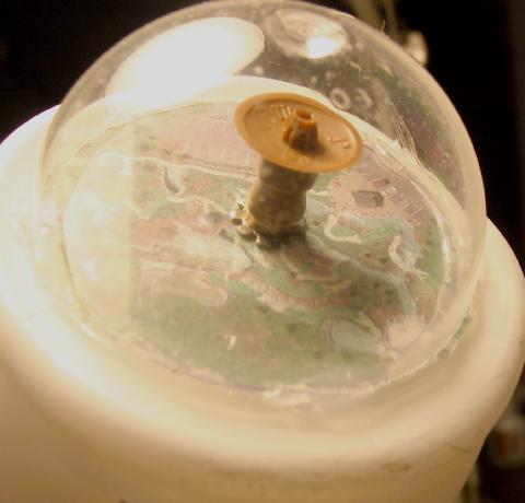
Constructing the Nose Cone and Dome:
Using a single serving plastic milk bottle, cut a hole in the screw on lid and press fit a used 24mm motor casing into it. The motor casing forms the nosecone shoulder. Glue the casing in place so the nozzle will be positioned inside the milk bottle when the cap is screwed on. Increase the opacity of the translucent bottle by spray-painting the inside of the milk bottle. By painting the inside of the bottle, there is no concern with future rough handling scuffing the paint.
The nosecone dome can be created by gluing a section of a gumball machine toy packaging to the top of the nose cone (base of the milk bottle). Before gluing on the dome, add details of the community life under the dome to the base of the milk bottle. I used an aerial photo of a miniature golf course to present a green space under the dome. A sparkplug tip was bolted to the top of the nosecone to help hold the laminated greenspace printout in place. A plastic disk was glued to the spark plug tip to serve as a scale deflector dish that protects the community from incoming cosmic rays.The dome was then hotglued to the milk bottle and laminated printout.
Recovery Harness Installation:
A length of elastic was attached to the top of the fishing leader, fed through the nosecone casing nozzle, and knotted inside the nosecone. A parachute is attached to a loop tied in the elastic.
 Flight Prep:
No positive motor retention was designed into this rocket, though a clip could be easily added under the superstructure if desired. The motor tube that extends below the edge of the fin roots allows for simple masking tape retention. The lack of a thrust ring in the motor mount allows use of E or D engines, without need for a length adaptor. Smaller engines can be press fit into a used 24mm casing.
The bulbous nosecone makes it necessary to put the mid-frame launch lug on a standoff. A short length of foamboard, glued through the superstructure to the central motor tube makes for a sufficiently rigid lug mount. The other lug is attached to one of the fins.
A small amount of cellulose insulation wadding is used to protect the chute.
Flights and Recovery:
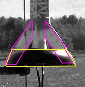
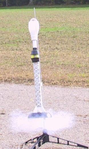
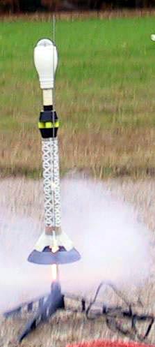
Thinking this was a relatively light rocket, I first tried a checkout flight on an A8-3. What was I thinking?! Big mistake. While it had a stable boost, the extremely draggy design kept the altitude quite low, and the rocket backslid to the ground. It ejected as it was falling over. The ring and one fin were knocked loose, which is why I re-engineered the ring attachment with notches and tabs and fin foaming. Mark that a stable flight and too long a delay…
The second flight was on a B6-4. This was a better flight, boosting straight, but the altitude was still unsatisfyingly low. The rocket came down nose first with the ejection just before touchdown, and no useful deployment of the parachute. The dome and re-engineered fins and ring took it in stride.
 |
 |
| Flight 1 | Flight 2 |
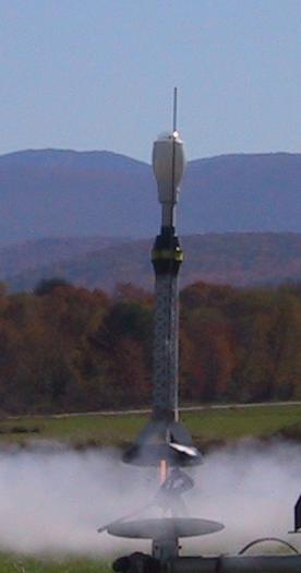
A third flight was on an E9-6 later that day. This was a great boost, arrow straight and to several hundred feet. The design was still so draggy that the rocket was well on its way down at ejection. The recovery stripped one shroud line, but the rocket landed with no damage.
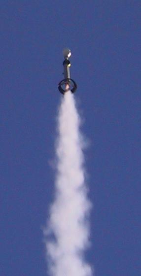
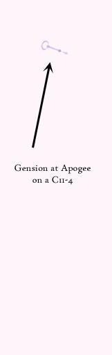
A third launch event took place to continue the search for the perfect engine for The Gension. A C11-3 was chosen as a compromise of long boost and short delay. This flight was the best yet, boosting straight, with ejection near apogee for a damage free recovery.
 |
 |