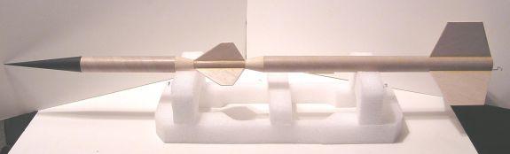
Scratch This End Up Original Design / Scratch Built
Scratch - This End Up {Scratch}
Contributed by Geoffrey Kerbel
| Manufacturer: | Scratch |
Brief:
This End Up turned out to be a fairly high performance 24mm bird. With an Estes
E9-6 engine, it has gone out of sight on the two launches with this engine.
Rocksim shows 1600' or more at my Phoenix, AZ launch site on a 90 degree day
with ~10% humidity. It has flown on engines as small as C6-5 with excellent
height and perfect recovery as well.
Construction:
The parts list:
- 1 Estes "E" engine kit or T-50 heavy wall tube, preferably foil lined (such as the T-50mf from Totally Tubular)
- 2 AR-5055 centering rings
- 1 AR-2050 engine block
- 1 New style E engine hook
- 1 BNC-55 nose cone
- 2 TA-2055 transition
- 1 BT-55 body tube, 18" long
- 1 BT-55 body tube, 7.5" long
- 1 BT-20 body tube, 4" long
- 1 1/8" thick x 4" wide medium to hard balsa sheet
- 1 24" long Kevlar® shock cord, 60 to 75# strength
- 1 36" long elastic or rubber cord shock cord
- 2 3/16" x 2" long launch lugs
- 1 18" 24" Estes or rip stop nylon parachute
- 1 screw eye
- 1 medium snap swivel
- 2 medium snap swivels
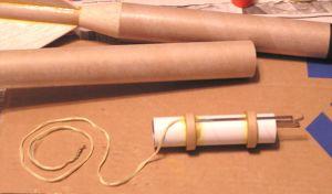
Begin construction with the engine mount. You will need the engine tube, the two AR-5055 rings, the AR-2050 engine block, and the E engine hook. Measure 1" from one end of the engine tube and make a mark with a pencil. Make another mark 5/8" from the other end. At the 1" mark make a 1/8" slit for the short end of the engine hook. Insert the engine hook into the slit. The engine hook should extend beyond the rear of the engine tube. Since the engine tube is a heavy wall unit, make sure you test fit the rings over the tube. They must slide on easily but not too loose or tight. The rings have to go over the engine hook as well. Use a hobby knife to remove one inside layer of the ring at a time until you get a snug fit if needed. When both rings are fitted correctly, install the lower ring up to the 5/8" mark and apply glue to both sides of the ring/tube joint and smooth the glue to a continuous fillet all around.
To attach the Kevlar® cord, feed 3" or 4" through the upper ring as you slide the ring down the engine tube and over the hook end in the slit. When the ring is in position at the 1" mark, loop the Kevlar® around the tube and tie into a knot. The Kevlar® can be left loose if you have trouble getting the knot in. As you apply the glue fillet, smooth the cord into the glue as you go around the ring. Carefully pull the loose end of the cord through the ring so there is no slack toward the front of the engine tube. See the engine mount picture to see how the cord and mount go together. When this has set up, install the engine block from the front of the engine tube, down to the engine hook tab and glue in place. Use an empty engine to slide the block all the way down and remove. Make sure there is no excess glue on the motor side of the tube by the block or your engine will not go all the way in and lock properly later. Tie the plain swivel to the free end of the Kevlar® cord. Set this assembly aside to dry.
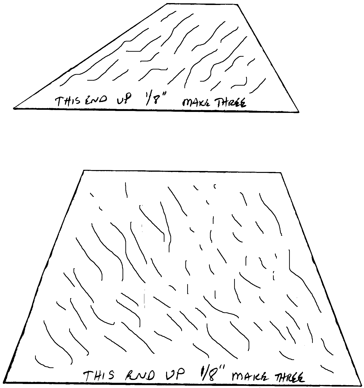
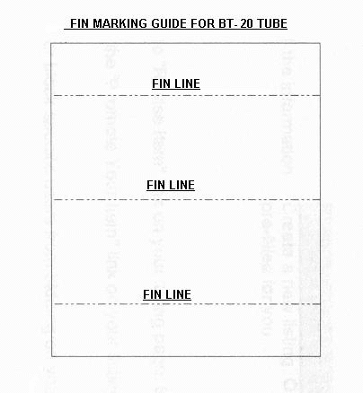
The upper unit combines the two transitions with the 4" BT-20 tube and the 7.5" long BT-55 tube. It is easier to finish sand the rocket if you lightly sand the tubes with 400-grit paper before gluing anything onto them. It also allows the glue to "bite" better (for a stronger bond). Cut out the small fins following the grain direction as shown and sand smooth, leaving all edges square for now. Take the BT-20 tube-marking guide, wrap it around the tube, and mark the tube for the three fins. They should be 120 degrees apart from one another. Use the nearest doorframe to extend the lines the full length of the tube. Use the glue of your choice, and attach the three fins to the tube one at a time. Use the great tip from EMRR's fin tip section to use a double glue joint. Spread a thin layer of glue on the root edge of the fin and let it dry. Then use another layer of glue over that to attach the fin to the tube. Make sure the fins extend straight out from the tube and be sure they are dead straight the length of the tube! The stable flight of this rocket depends on these fins being aligned properly! They are high enough on the body to influence the rocket to fly straight or wherever it wants to!
After the glue has set up, sand the fin leading edge round and the trailing edge to a taper. Do not sand too much off! You just want to give the fins a little better airfoil shape. Finish the fin/tube joint with a smooth, full-length fillet on both sides of the fins, again this is a great little tip from EMRR fin tip section. Let the fillets set up and use your favorite balsa grain filler on the fins at this time and fill and sand until the grain is filled and smooth. Do all this sanding now before attaching the transitions. Once the transitions are glued on, they will get chewed up by the sandpaper or your fingernails as you sand the fins if you are not careful while sanding. I had quite a bit of repair to do to them because I glued it all up and then started the airfoil sanding.
When you have the fins finished how you want them, lightly sand the transition BT-55 side flat and glue the BT-20 side to the top and bottom of the tube with the fins. Again, make sure these are on straight with the tube at both ends. Before the glue sets up, stand the unit upright and use a T-square or an L shape ruler on a flat surface and along the face of each fin to check the alignment. Flip the unit over onto the other transition and check again. Adjust transitions as necessary and let dry.
You can now glue on the 7.5" BT-55 tube to the front of the fin assembly transition. Make sure this is on straight with the fin tube! When this is dry, test fit the nose cone to the tube. I fit mine on fairly tight without glue so I could use the large tube as a payload section if I want to later. The choice is yours to glue it on or not. Screw in the eyelet to the lower transition, remove and squirt some glue into the hole, and reattach the eyelet to the transition. The upper body is now assembled.
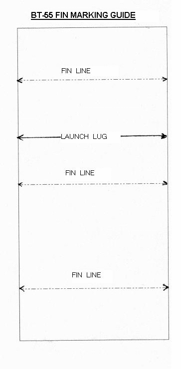
The lower tube assembly is straightforward tube and fin rocket build. Lightly sand the tube with 400 grit sandpaper. Use the BT-55 fin-marking guide to make a mark for each of the fins and the launch lug locations. The fins should be 120 degrees apart. Use the doorframe to again extend the mark from the end of the tube to about 6" up for the fins and full length for the launch lug. Follow the same procedure as the other fins for cutting out, sanding smooth and attaching them to the tube. When all the fins are dry, fillet them on both sides and be a little generous with the fillets. I had a large amount of fin flutter on the first flight which resulted in some cracked fillets. I solved the problem by using a tip from EMRR's fin tip section of soaking the fins with some thin CA on all sides and adding an extra layer on the fillets. I found I was also using balsa that was too soft. I would recommend the bottom fins to be from hard balsa. Thin basswood (3/32") would be good as well. When everything is dry, sand the fins to a smooth airfoil shape same as the upper fins and fill the grain until smooth all over. Install the launch lugs on the LL line with the lower one 2" up from the bottom of the rocket and the other one 12.5" up from the bottom. Make sure they are aligned with each other and a launch rod slides smoothly through both before they set up.
Last up is the installation of the motor mount into the lower body tube. Turn the body tube fin side up and let the swivel and cord slide down through the tube if you are using the Kevlar® cord. Test fit the motor assembly into the tube with the engine hook lined up with the launch lug line. If both rings don't slide in smoothly, lightly sand the outside of one or both to get a snug fit. Before you insert the motor mount assembly, run a ring of glue inside the tube about 2" and slide the motor mount into the body tube. Just before the first ring gets to the glue you just put in, stop and run another ring of glue inside the body tube near the bottom. Now in one continuous motion, insert the motor assembly fully into the body tube so that both tubes are nearly flush with each other on the bottom. Make sure the engine hook is aligned with the launch lug line. If using the Kevlar® cord on the mount, pull it out of the tube gently and let it hang out so it does not have a piece of it stick to the glue from the upper mount ring that is inside. This extra glue step really makes for a strong motor mount. When the mount has set up, run a fillet of glue around the bottom of the body tube/motor mount ring and let dry.
For the Kevlar® cord mount, tie one snap swivel to the elastic or rubber shock cord with at least two square knots and tie the other end to the eyelet on the upper body tube transition with at least two square knots as well. Three knots each would be better. Attach the snap swivel to the swivel on the end of the Kevlar® cord. Attach the other snap swivel to the chute lines of whichever chute you are going to use depending on field size and wind conditions. Attach the chute snap swivel to the eyelet and pack both the chute and the shock cord into the lower body tube and fit the two tubes together.
Finishing:
I use thinned out Elmers Fill 'n' Finish over the entire rocket. The sanding is
a bit much but the stuff sands really easy and fills the balsa and the tube
spirals nicely. Use it sparingly though! I used Krylon paint and their clear
coat on all my rockets. The paint goes on smooth and dries remarkably fast. It
also does not react with the decals I use. I used the brightest orange I could
find and trimmed it with gloss black. After
the custom decals are put on, I
covered the entire rocket with Future Floor Polish. Using a large soft brush
with light strokes will give you an incredible smooth and shinny finish. When
finished, I was surprised to find that the bird weighed in at a svelte 3.9oz
without an engine in it.
Flight:
The rocket was test flown before finishing with a C6-5 engine in an adapter for
the first flight. It took four to six pieces of standard Estes wadding or about
two inches of flameproof cellulose to protect the chute. This flight and the
next both had some stability problems, which turned out to be a very slight
misalignment of the upper fins. Since the bird was unfinished at this point, I
stripped off the fins and made sure they were on straight this time. That is
why you need to be extra careful when assembling the upper fins on to the small
tube. The next flight was picture perfect and I decided the next flight was
going to be with a C11-3.
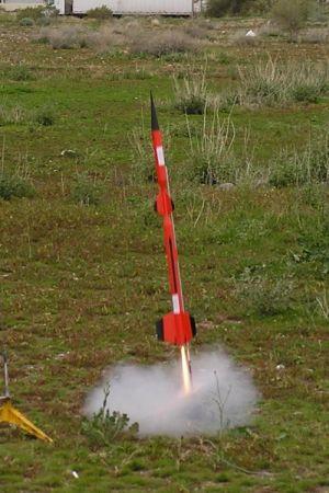
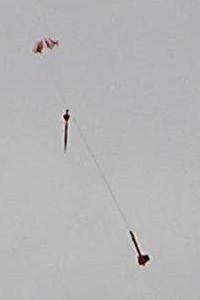
This flight surprised me as the rocket shot off the launch pad and headed straight up. The C11 may not have much thrust duration but it is powerful! The ejection charge was a little too soon but recovery was without problems although there was two chute lines that separated. The C11-5 would be a better choice of engines and this combination could be used in a small field depending on wind drift conditions. At this time with the rocket flying well, I finished it and painted it.
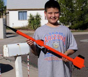
The next flight was with a D12-5 in a larger field and the rocket really showed what it could do. Nice high, straight flight with ejection just barely past apogee. Perfect recovery approximately 100 yards away from launch pad. Estimated height of 600+ ft. Although I had built it to fly on E engines, I was a bit worried to do so. Since things seemed to be just fine, I pasted some "if found please call..." stickers on it and loaded up the E9-6 for its last qualifying flight. What a launch!!! The bird lifted off at a nice, easy rate and then started to gather a head of steam. It seemed like an hour before the engine cut out and about half way up I completely lost sight of it. The only hint of where it went was when I spotted the coast trail and then I lost it again. Since the winds were very light and I had an idea where it was heading, I kept the camera in the general area of where I thought it would be. It took about 15 seconds to pick it up and I could see it was coming down with a perfect chute but it was really drifting over and away. My son was able to recover it just fine but he had about a 1/4 mile walk to get it back. Estimated height was in excess of 1200 ft!
Summary:
The nice part about this rocket is the many types of engines you can use
depending on your flying field size. With a separation in the middle, it can be
split and transported as a much smaller package and the upper tube has enough
room for a small payload.
 |
 |