Scratch Titan Interceptor Original Design / Scratch Built
Scratch - Titan Interceptor {Scratch}
Contributed by Geof Givens
| Manufacturer: | Scratch |
Brief:
This is a 1/21 scale model of the infamous Titan Interceptor, which shot down
more Terran fighters than any other ship during the second Saturnian war of
2716-2721. Although clumsy by today's standards, this ship fascinated
Earthbound scientists and the general public when Lt. Molly Kanoshita managed
to lash a damaged TI to her ship and execute a controlled crash landing at
Terran Marsbase Seven. Analysis of this craft led to weapons innovations that
turned the tide of the war, but of course it was Lt. Kanoshita's capture of the
crew--three Sino'oan pilots--that electrified the public and yielded the
holovid footage seen by schoolchildren of every generation since then. The
Sino'oan race did not evolve on Titan, but are believed to have begun settling
on Saturn's largest moon sometime in the early 24th century, based on
archeological evidence. Today, the ship captured by 'Samurai Molly' is still on
display at the Tokyo branch of the Smithsonian. The one surviving Sino'oan
pilot reportedly died of his injuries within days of capture. Eight months
later, authorities reported that the bodies of all three pilots had been
destroyed in an accidental lab fire, although this remains a source of tension
in Terran-Sino'oan relations to this day.
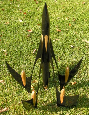
This is my second scratch design. It is a 5-fin futuristic design with the boat tailed engine compartment at the base of a central shaft far ahead of the major fin surfaces, which hang from struts attached near the rocket nose. It is designed for 24mm single use motors and has parachute recovery. The rocket is 24 inches tall and weighs 10 5/8oz.
Construction:
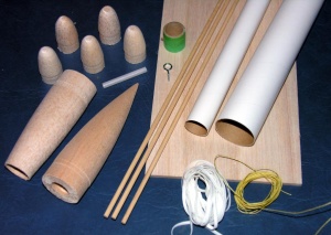
This project was a long, careful, and intricate build. Most parts were obtained
mostly from Balsa Machining Service. BMS offers a fantastic variety of parts,
including the ability to order custom designed fins and nose cones. However, I
was disappointed in the quality of the parts I received. The 5
"identical" nose cones were very different, ranging from a rounded
tip to 3/8 inch flat top. Quite a lot of sanding was required to make them
uniform. The engine end of the boat tail was frayed and chipped, requiring
repair for a clean look. None of the balsa shoulders fit in the corresponding
tubes without sanding and many of the turned balsa pieces had very rough
finishes--sometimes almost shaggy. Since all of this is repairable with enough
filling, sanding and sealing. I will order from BMS again when I need custom
parts, but the quality was variable, at least in this order.
The large fins and small fin buttresses were cut from templates. An unusual, diagonal grain alignment was chosen to minimize the chance of breaking fin tips. Next, I rounded and beveled the edges of the large fins before bisecting each to glue in the dowel. Thus the dowels actually run from the body tube to the trailing edge of the large fins to provide additional strength. The fin/buttress/dowel assembly was next glued together.
 The
trickiest part was the construction of the weapons on each fin. These are
cylindrical, but fade to a smooth transition near the bottom of the fin. Thus,
I needed to remove two portions of the tube, each of which was the width of the
fin at the top and gradually increasing in width until they joined at the
bottom. This leaves a leading ring of tube with two dangling parabolas on
opposite sides to be draped over the fin. The parabolic portions could then be
slightly bent and glued flush with the fin. To determine a template for these
cuts, I used a dark room. With a flashlight, I projected the shadow of a
straight edge onto a body tube (wrapped in paper) in a manner so that the upper
and lower ends of the shadow matched pre-measured marks on the tube. I then
traced the curved edge of the shadow on the tube. Then I removed the paper from
the tube and smoothed out the tracing a bit by eye. By folding the paper, I
reflected my tracing to get the other half of the parabola. This yielded the
basic template, which I then used to cut portions from 5 cylinders. The leading
areas of these tubes required a little more work. First, the removed material
runs different distances up the tube because the outer and inner sides of the
fin leading edge are at different heights. Second, the removals must contour
the rounded leading edge of the fin for best fit. Third, I cut some lines
partially across the dangling parabolas to relieve stress and prevent crumpling
when they were bent to glue to the fin surface. These seams were smoothed with
filler later.
The
trickiest part was the construction of the weapons on each fin. These are
cylindrical, but fade to a smooth transition near the bottom of the fin. Thus,
I needed to remove two portions of the tube, each of which was the width of the
fin at the top and gradually increasing in width until they joined at the
bottom. This leaves a leading ring of tube with two dangling parabolas on
opposite sides to be draped over the fin. The parabolic portions could then be
slightly bent and glued flush with the fin. To determine a template for these
cuts, I used a dark room. With a flashlight, I projected the shadow of a
straight edge onto a body tube (wrapped in paper) in a manner so that the upper
and lower ends of the shadow matched pre-measured marks on the tube. I then
traced the curved edge of the shadow on the tube. Then I removed the paper from
the tube and smoothed out the tracing a bit by eye. By folding the paper, I
reflected my tracing to get the other half of the parabola. This yielded the
basic template, which I then used to cut portions from 5 cylinders. The leading
areas of these tubes required a little more work. First, the removed material
runs different distances up the tube because the outer and inner sides of the
fin leading edge are at different heights. Second, the removals must contour
the rounded leading edge of the fin for best fit. Third, I cut some lines
partially across the dangling parabolas to relieve stress and prevent crumpling
when they were bent to glue to the fin surface. These seams were smoothed with
filler later.
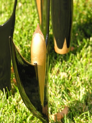
The fin assemblies were completed with more filling, sealing, and sanding to make them appear like one seamless piece. I must admit that my fifth one was much better than my first attempt! At the last minute, I added some pointy blades to the nose of each weapon for extra flourish.
The main body tube and engine compartment are assembled in an ordinary fashion. The boat tail allowed direct attachment of the recovery system to a screw-eye in the boat tail.
 A 1/4
scale cardboard cutout of the final model suggested that the CP was perhaps
2.75 inches up from the rear edge of the boat tail. Now I was in a quandary: I
couldn't determine the CG until the fins were attached, but I didn't want to
attach the fins until I had determined the final length of the central body
tube since I wanted the fins to join the tube at an aesthetically pleasing
distance from the nose cone. I had planned to lay all the fins as a group along
the body tube (affixed with a rubber band), since this should accurately place
their weight along the major axis of the rocket, ignoring their outward
hanging. However, I don't know enough physics to know if that would be
appropriate, since the actual design has the fins attached up by the nose with
the majority of the fin weight down by the tail. Does the point of attachment
influence how/where the weight acts? Some experiments with rigid assemblies of
household objects suggested that the answer is no. Second, the body tube was
still 36", and I knew I wanted more like 10", so without cutting I
would have to play some math and balancing games to compensate for the extra
length when finding the CG for the planned shorter length. Anyway, having thus
guesstimated a tube length yielding a stable CG, I made the final cut, figuring
I had enough lead weight for the nose cone if I had badly miscalculated.
A 1/4
scale cardboard cutout of the final model suggested that the CP was perhaps
2.75 inches up from the rear edge of the boat tail. Now I was in a quandary: I
couldn't determine the CG until the fins were attached, but I didn't want to
attach the fins until I had determined the final length of the central body
tube since I wanted the fins to join the tube at an aesthetically pleasing
distance from the nose cone. I had planned to lay all the fins as a group along
the body tube (affixed with a rubber band), since this should accurately place
their weight along the major axis of the rocket, ignoring their outward
hanging. However, I don't know enough physics to know if that would be
appropriate, since the actual design has the fins attached up by the nose with
the majority of the fin weight down by the tail. Does the point of attachment
influence how/where the weight acts? Some experiments with rigid assemblies of
household objects suggested that the answer is no. Second, the body tube was
still 36", and I knew I wanted more like 10", so without cutting I
would have to play some math and balancing games to compensate for the extra
length when finding the CG for the planned shorter length. Anyway, having thus
guesstimated a tube length yielding a stable CG, I made the final cut, figuring
I had enough lead weight for the nose cone if I had badly miscalculated.
The rest was easy. I made several jigs to glue on the fin assemblies. A little more fiddling for the recovery system and so forth and I was done.
Finishing:
In my head, I had always seen this rocket as mainly silver or some other very
light metallic color of blue, violet, or champagne. After a brief dalliance
with lime green, however, I ended up choosing to finish it black to make it
look really mean and then with several coats of clear over the top. Some of my
daughter's sparkle glue added a nice touch.
Flight:
Then it was out to the backyard for the swing test. After adding 1oz nose cone
weight, it flew just like a badminton birdie. I was ready for launch, but by
this point my kids were teasing me that I "loved the rocket too much"
to fly it. What the heck, these things are mean to CATO eventually. Let 'er
fly!
One lesson I learned with this scratch build is to plan better at the start about what the final weight will be and what engine will be used. The final weight (without motor) was 10 5/8 oz. This left me in a quandary because a motor with 20Ns total thrust would keep the rocket low but probably fail to attain minimal safe velocity leaving the launch rod. A motor with 40Ns would leave the launch rod safely but fly at least 1100 feet. With an extra large parachute and limited area, I wasn't sure I wanted to send my treasured model quite so high. In the end, I opted for low and slow, choosing an AeroTech D21. This crammed so much of the thrust into the start that the launch rod velocity was estimated to be 42ft/s. The estimated total altitude was a modest 415ft. I had to build a 18mm engine adaptor out of an old D12 casing because I had built the model for 24mm motors.
The D21 provided ample power to get the rocket off the pad. The rocket accelerated upward, stable, with no spin, for the first 150 feet. At this point, velocity was so great that the fin assembly started vibrating/fluttering. Quickly, the fluttering grew so severe as to destabilize the rocket. Amazingly, the resulting crash under a semi-deployed chute only chipped a few fin tips. (The fluttering also "shook off" paint chips over major portions of the fin assemblies.)
Summary:
This was a good learning experience for me, because it was not a failure mode I
had anticipated. Given the initial boost of the rocket, I believe that a
similar design might work if the fin arms were made of a much more rigid
material and/or they were braced to prevent horizontal wobble. Status: damaged
and retired.
 |
 |