Scratch Tube Lifter Original Design / Scratch Built
Scratch - Tube Lifter {Scratch}
Contributed by Peter Stanley
| Manufacturer: | Scratch |
Brief:
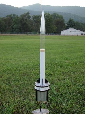
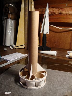
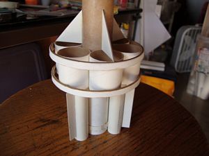
The Tube Lifter is a two-stage fin, tube, and ring tail rocket. Sustainer is recovered with a 14" parachute, and
booster via tumble recovery. It has a clear payload bay.
Construction:
The parts list:
- PNC-55AC Nose cone
- 5" Clear - BT-55 tube, from Semroc
- 20.0" BT-55 tube
- 1.28" x 1.0" Balsa Bulkhead
- 1/16" Staples brand illustration board
- 4 BT-50 to BT-55 centering rings
- 20" BT-50 tube
- 14" nylon chute
- 2 1/4" pieces of 4" FedEx tube
- 15" 400lb Kevlar® cord
- 10" x 1/8" elastic
- 1/8" x 2" launch lug
- 2 motor hooks
- 1 small screw eye
- 0.75oz of nose weight
- 24mm to 18mm motor adapters (optional)
Click to download fin temples for the forward fins and aft fins.
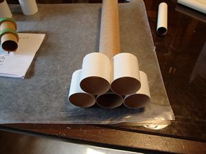
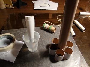
The Tube Lifter is quick and easy to build. The fins are cut from 1/16" presentation board and require no extra finishing besides for primer and paint. The tube fins for the sustainer were glued two at a time on a flat surface. The tube rings are cut from 4" diameter FedEx tube. That type of tube fits perfectly around a BT-55 tube fin configuration. The method I used to cut the 1/4" rings is similar to how I cut body tube in general. I made a guide with two pieces of cardstock paper wrapped around the end of the tube, recessed slightly more than 1/4" from the end. I used a razor saw and worked my way around in a circular fashion until I cut through the tube.
The motor mounts were built as most standard kits, except the sustainer mount requires the bottom of the lower centering ring be located 3/4" from the bottom of the motor tube.
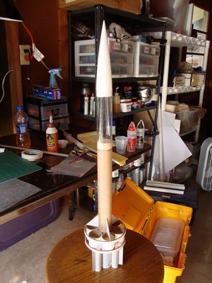
I friction fit the nose cone into the forward end of the clear payload bay using tape. The lower end has a balsa bulkhead glued in with thin CA.
I used 0.75oz of lead shot for the nose weight and fixed in place with 30 minute epoxy. When using epoxy in nose cones, it is important to keep the nose cone cool while the epoxy cures otherwise it can warp the nose cone. I kept it cool by placing the nose cone pointed down in a cup of water.
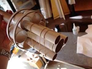
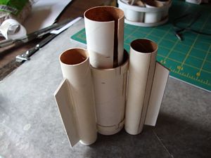
The booster connects to the sustainer in two ways. The motor mounts connect via a sleeve, which is made from BT-50 tube that is cut lengthwise. The bottom half is glued to the exposed end of the booster motor tube. The forward end slides around the lower part of the sustainer motor tube. To protect against exhaust flame, I coated the inside of the sleeve with thin CA and the outside with 30 minute epoxy. This also adds some strength. The second connection point is made by the booster tube fins. The booster tube fins are made from BT-50 tube that slide inside 3 of the sustainer tube fins. I cut two 1/4" pieces of BT-55 tube lengthwise and wrapped around the main booster tube. This served as a standoff for the booster's tube fins. The boosters tube fins are aligned by first connecting the motor tube sleeve, then placing the booster tube fins inside three of the sustainer tube fins, and are held in place against the booster body tubes standoff sleeves with rubber bands. Once everything was in place, I tacked the booster tubes to the standoffs with 5-minute epoxy. After that set I reinforced with more epoxy.
The shock cord was made from 400lb test Kevlar® tied to the sustainer motor tube with the other end tied to a 10" piece of 1/8" elastic.
Finishing:
Most people would probably fill in the body tube spirals, but I skipped that and just painted everything with a coat of
white primer. I then painted the sustainer body with white paint. I hand painted the sustainer/booster fins and
sustainer rings with black acrylic. I used Krylon aluminum for the nose cone and booster section.
Flight:
The first flight was perfect. I used 24mm to 18mm adapters and flew it on a B6-0 to a B6-4. The staging worked great
and there was no damage to the booster or sustainer. One major advantage of this design is it can fly on a wide range
of motors. The second flight was on a B6-0 to a B4-4. That too, was a perfect flight and recovery. I flew it as a
single stage on a C6-5 for the third flight. It arched over slightly and delay was way too long for that rocket. The
chute was deployed about 2.5 to 3 seconds after apogee. A C6-3 would have been better. I didn't have any C6-3s, so I
tried again but used a B6-0 booster. It arched over again as the previous flight, and delay was too long. I attribute
the arching over to a too short, flimsy launch rod and moderate wind. I plan to fly this on 2 D motors at the next
launch.
Recovery:
The 14" nylon parachute that I used seemed optimal, but a smaller chute might be needed in stronger wind,
especially when flown to higher altitudes. The last two flights deployed at a high speed and there was no zippering.
One of the booster's tube fins did get a little squashed after the last flight.
Summary:
I wanted to build a unique looking two-stage rocket that would be fairly easy and simple to build. I was a little
concerned about the stability of the design, but after flying it, I am mostly pleased with how it performs.
 |
 |