Scratch Upscale Big Brute Original Design / Scratch Built
Scratch - Upscale Big Brute {Scratch}
Contributed by Dick Stafford
 Brief:
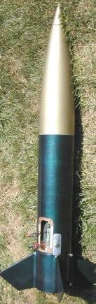
My first mid-powered rocket was the North Coast Big Brute (pre-Estes). I love
stubby rockets and when it came time to decide how to use some of the
5.38" tubing that I won from LOC, an upscale Big Brute was the natural
decision. I decided to incorporate several features I'd been wanting to try,
including: air starts, electronics mounted in the rocket's fin unit, a window
to allow me to see the G-Wiz altimeter's LEDs, and an ejection cannon based on
¾" PVC fittings. My upscale has a central 38mm mount with two 29mm
and two 24mm motor mounts.
Construction:
- One LOC 5.38" tube, 24" long
- One LOC 5.38" coupler, for the inner lining of the electronics bay
- One LOC 38mm MMT tube, 12" long
- Two LOC 29mm MMT tubes, 6" long
- Two LOC 24mm MMT tubes, 6" long
- 10.5mm tubing, 6" long, for the air start igniter conduit
- One LOC 5.38" LONG nose cone
- Three LOC 38mm-5.38" centering rings, two of which were custom drilled for the outboards by Performance Hobbies
- Four 3/16" plywood fins, custom cut by Performance Hobbies
- One LOC ½" launch lug
- Two 1500-series Delrin rail buttons from railbuttons.com (Matt's Railbuttons)
- One 38mm Slimline motor retainer from Giant Leap
- One ¾" PVC threaded adapter
- One ¾" PVC male plug
- Four small pieces of coat hanger wire, used to insure the PVC coupler is affixed solidly
- Misc. nuts, bolts, and washers for retention of 29mm and 24mm motors
- Misc. 3/16" plywood for in the electronics and ejection bays
- Misc. plywood, basswood, hardware for mounting electronics, connectors, etc.
- Clear plastic from a suitably sized plastic jar for electronics hatch window
- Audio quick connect terminal for ejection and air start igniters
- One multi-pole key switch (Aerocon Type 2 switch)
- One Aerocon 'Remove Before Flight' ribbon
- Eight socket head sap screws for hatch door retention
- Ten small nuts and bolts to attach the clear plastic view port and the key-switch plate
- Recovery system from other projects: 15 feet of ¾" tubular nylon, Giant Leap Kevlar® cord protector, 24" diameter chunk of a car air bag, Aerocon 66" chute, two large quick-links
- Adjustable
Nose Weight Assembly with Spanner Driver
- 2-inch mailing tube (20.5") with telescoping tube (21") from The Container Store
- ¼-20 threaded nylon rod from Fastenal
- Four ¼-20 nylon nuts
- ¼" aircraft plywood, enough for two 5 3/8" bulkheads, and three 2" bulkheads
- Stainless steel U-bolt, ¼-20 thread, 1.5" x 2", with four nuts and four washers
- ¼" wooden dowel, ¾" long x 2
- 3/8" brass tubing, 2" long
- 2-part expanding foam from Giant Leap
- 1 lb, No. 7 ½ lead shot
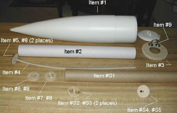
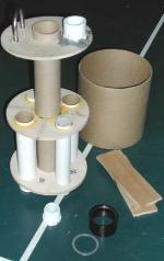 This photo shows the components
of the motor mount assembly (top and bottom rings are dry-fit). As you can see,
the 38mm motor mount extends to the third centering ring and the other tubes,
including the 10.5mm wiring conduit only run between the lower two rings. These
rings sandwich the fin tabs of the fins. I added small bolts to the lower ring
to serve as attachment points for outboard motor retention. Since I plan to use
SU motors for the outboards, I probably will not use positive motor retention,
but I included them in case I ever want to use reloadable motors. The Slimline
retainer will be installed after the rear centering ring is installed, which
will itself be installed after the rest of the motor mount, fins, and
associated internal fillets.
This photo shows the components
of the motor mount assembly (top and bottom rings are dry-fit). As you can see,
the 38mm motor mount extends to the third centering ring and the other tubes,
including the 10.5mm wiring conduit only run between the lower two rings. These
rings sandwich the fin tabs of the fins. I added small bolts to the lower ring
to serve as attachment points for outboard motor retention. Since I plan to use
SU motors for the outboards, I probably will not use positive motor retention,
but I included them in case I ever want to use reloadable motors. The Slimline
retainer will be installed after the rear centering ring is installed, which
will itself be installed after the rest of the motor mount, fins, and
associated internal fillets.
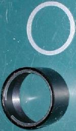 The PVC coupler (i.e. the
ejection cannon) and U-bolt have already been installed in the upper ring.
Initially, I was worried about two things: the cannon blowing back into the
bay, and the cannon twisting when the ejection plug is screwed in. The first
item should not be an issue because the coupler has protrusions, presumably to
allow a wrench to attach. Although epoxy alone might have solved the twisting
issue, the plugs do get pretty tight and I'd hate for it to twist rather than
unscrew. So, I drilled four small holes into the side of the coupler, ahead of
where the plug would seat. I also cut corresponding notches into the centering
ring. Four small pieces of coat hanger wire fit into the holes and then down
into the notches. I still epoxied it in, using JB Weld on one side and 30
minute Bob Smith on the other (leftovers from other jobs). That coupler isn't
moving now!
The PVC coupler (i.e. the
ejection cannon) and U-bolt have already been installed in the upper ring.
Initially, I was worried about two things: the cannon blowing back into the
bay, and the cannon twisting when the ejection plug is screwed in. The first
item should not be an issue because the coupler has protrusions, presumably to
allow a wrench to attach. Although epoxy alone might have solved the twisting
issue, the plugs do get pretty tight and I'd hate for it to twist rather than
unscrew. So, I drilled four small holes into the side of the coupler, ahead of
where the plug would seat. I also cut corresponding notches into the centering
ring. Four small pieces of coat hanger wire fit into the holes and then down
into the notches. I still epoxied it in, using JB Weld on one side and 30
minute Bob Smith on the other (leftovers from other jobs). That coupler isn't
moving now!
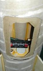
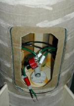
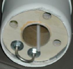
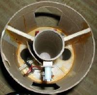 The electronics and ejection
charge bays are located 180 degrees apart and between the top two rings. The
next photo provides a top view of these bays. One bay provides access to the
ejection cannon and the conduit for the air starts, and the other holds the
electronics. The hatch door for the electronics bay will have a clear window so
the LEDs on my G-Wiz Deluxe will be visible. These bays are isolated from one
another by two bulkheads, in case gasses enter through the air start port or
leak from the ejection cannon. With the exception of the epoxies used for the
ejection cannon, the entire motor mount/electronics bay assembly was
constructed using Titebond II wood glue.
The electronics and ejection
charge bays are located 180 degrees apart and between the top two rings. The
next photo provides a top view of these bays. One bay provides access to the
ejection cannon and the conduit for the air starts, and the other holds the
electronics. The hatch door for the electronics bay will have a clear window so
the LEDs on my G-Wiz Deluxe will be visible. These bays are isolated from one
another by two bulkheads, in case gasses enter through the air start port or
leak from the ejection cannon. With the exception of the epoxies used for the
ejection cannon, the entire motor mount/electronics bay assembly was
constructed using Titebond II wood glue.
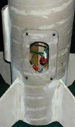
 I found the LOC
tubing was much easier to cut with an Exacto knife than I expected. I had no
problem cutting the fin slots and hatches. To make sure there were a good fit
during final assembly, all the hatches and corresponding holes were marked,
including their up/down orientation. I tried to be careful in my measurements,
but each varied slightly. I also made a minor error and placed the hatches a
little lower than I had wanted. Luckily, this isn't really a problem. The edges
of the hatches and openings were all treated with thin CA prior to
sanding/smoothing. To cut the corresponding holes on the coupler, I inserted it
into the main tube and traced the hatch outlines. I then drew lines
½" in from each edge, which formed a lip to support the hatch doors.
I found the LOC
tubing was much easier to cut with an Exacto knife than I expected. I had no
problem cutting the fin slots and hatches. To make sure there were a good fit
during final assembly, all the hatches and corresponding holes were marked,
including their up/down orientation. I tried to be careful in my measurements,
but each varied slightly. I also made a minor error and placed the hatches a
little lower than I had wanted. Luckily, this isn't really a problem. The edges
of the hatches and openings were all treated with thin CA prior to
sanding/smoothing. To cut the corresponding holes on the coupler, I inserted it
into the main tube and traced the hatch outlines. I then drew lines
½" in from each edge, which formed a lip to support the hatch doors.
The electric matches for both the ejection charge and air starts connect to the quick connect speaker connector. The wiring for this connector runs through one of the bulkheads to the ejection charge bay. One leg of each of the leads is switched via a multi-pole key switch. From there, the leads will be attached to the connectors on the G-Wiz. The G-Wiz is mounted on a small G10 plate that mates with two bolts that are permanently affixed to a basswood strip in the electronics bay. The G-Wiz will operate in a dual battery configuration to help ensure the air starts light reliably. A small niche was formed to the side of the G-Wiz mount. The batteries will sit in this niche and will be wedged-in with some heavy foam rubber. I've used this stuff to hold the G-Wiz before - it successfully protected it from a 2000' free-fall when my Crusader's payload bay came off the recovery system. In the ejection bay, the audio connect is bolted to two plywood stands which in turn are glued in.
 The key switch
consists of a metal key latch that is mounted to the side of the airframe with
a retaining screw. The actual switch pops onto this key latch from the rear.
Because the switch itself is larger than the opening for the key latch, it
would not be easy to remove after the two parts are snapped together.
Therefore, I mounted the switch assembly to the small piece of tubing that was
removed to form the view port in the electronics bay door. A hole large enough
to accommodate the switch was cut in the airframe and the switch plate was
bolted to the airframe. The wiring was all soldered, installed, and fully
verified before the motor mount/electronics bay assembly was glued into the
airframe.
The key switch
consists of a metal key latch that is mounted to the side of the airframe with
a retaining screw. The actual switch pops onto this key latch from the rear.
Because the switch itself is larger than the opening for the key latch, it
would not be easy to remove after the two parts are snapped together.
Therefore, I mounted the switch assembly to the small piece of tubing that was
removed to form the view port in the electronics bay door. A hole large enough
to accommodate the switch was cut in the airframe and the switch plate was
bolted to the airframe. The wiring was all soldered, installed, and fully
verified before the motor mount/electronics bay assembly was glued into the
airframe.
I was going to use both threaded inserts and small socket head cap screws to hold the hatch doors on. However, after I drilled the holes and test fit the doors, they seemed to be attached soundly with only the screws attached. So, I treated the holes with thin CA, re-drilled them because of swelling, and reinserted them. I think they will be fine and, if the loosen over time, I will add the threaded inserts.
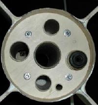 I glued the motor
mount/electronics bay assembly into the airframe using West epoxy. This allowed
plenty of time to align the hatch opening. I also poured some epoxy onto the
top centering ring to create a hefty fillet between that ring and the airframe
and main motor tube. Originally, I was going to use epoxy fillets inside the
fin can area. Instead, I ended up adding dowels and wood glue. The thick
outside fillets are epoxy. This photo shows a bottom view of the rocket after
the rear CR was glued in.
I glued the motor
mount/electronics bay assembly into the airframe using West epoxy. This allowed
plenty of time to align the hatch opening. I also poured some epoxy onto the
top centering ring to create a hefty fillet between that ring and the airframe
and main motor tube. Originally, I was going to use epoxy fillets inside the
fin can area. Instead, I ended up adding dowels and wood glue. The thick
outside fillets are epoxy. This photo shows a bottom view of the rocket after
the rear CR was glued in.
At this point, I weighed the rocket and updated my sims. The refined sims said that I needed up to a pound of extra nose weight for a J350 with 2 G80's. Since I want to be able to re-use this fairly expensive nosecone on a future project, I decided that I didn't want to glue in a fixed amount of weight. About that time, I learned of an adjustable nose weight assembly designed by Steve Pasquier. He provided me with the plans and it fit my needs well. I also learned he had submitted the plans to EMRR, and they were since published here.
I will refer the reader to Steve's article, and will merely outline some of the changes I made and provide some lessons-learned. The figure above shows the parts before assembly. The next photo shows the assembly installed. The parts numbering is per that review. Now, the changes:
I used a 2" mailing tube in place of the prescribed motor mount tubing because it was inexpensive, had a telescoping inner tube, and was quickly available. The applicable changes were made to the centering rings, etc.
I made a ½" bulkhead from two ¼" bulkheads epoxied together. These were cut with my RotoZip.
A 2" hole was cut in these rings with a circle cutter attachment for my hand drill- an added perk for using the 2" tubing. These smaller circles represented two of the five required bulkheads. Three additional 2" bulkheads were cut with the circle cutter.
I used a piece of brass tubing in place of a dowel for the bar that is used to attach to a drill chuck. In my nose cone turning activities, I have found this to be a better material.
The Adjustable Nose Weight Assembly and Spanner-Driver tool were easy to make, here are some notes:
Read all the instructions and understand the operation of these items before you start (motherhood, right?)
Care must be taken to make sure all the holes in the smaller bulkheads (2" in my case) are perpendicular to minimize eccentricity when the tool is turned with a drill. This is pointed out in the instructions but I want to reiterate it. Despite using an attachment on my drill to make sure the holes were true, a couple were off and took some adjustment (sanding, filling, etc.). A drill press would be best of course.
When I bought my nylon all-thread, I got a 6' length from Fastenal. They were cheaper than McMaster-Carr, and they had a local store. However, they must have shipped it rolled up as it arrived looking like a piece of limp spaghetti. I wasn't happy, but was anxious to proceed so I accepted it. When I glued the bulkhead with all-thread (items #4 & #5), I centered it with both of the other bulkheads (#6 & #7). It still was bent, so I left about ½" extending out of the tube, which makes it easy to start the threaded bulkheads and insert the spanner-driver. If this was down in the tube and bent, it would be almost impossible to do so.
Finishing:
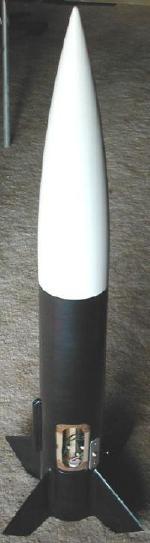 The airframe was
not glassed so the spiral lines were filled with Fill 'n Finish. Somehow, I
messed up slightly on about half of the outer fillets and had to fill them with
a mix of epoxy filler and Fill 'n Finish. I used Krylon primer as the base
coats and then painted the body using purple/green Duplicolor Mirage, and the
nose cone with Rustoleum Hammered Gold. The body, and hatch doors were painted
separately. The hatches and other holes were all covered with masking tape
during the painting process to keep paint out of the bays. I also masked the
motor tubes and retention hardware on the business end. Finally, the
switch-plate is painted with Krylon chrome to make it stand out. One caution
with the Mirage paint: heed the warnings about humidity! I was impatient to get
the rocket done and there are a lot of small spots in the paint. This didn't
happen the first time I used it, so I surmise it was due to the ambient
conditions.
The airframe was
not glassed so the spiral lines were filled with Fill 'n Finish. Somehow, I
messed up slightly on about half of the outer fillets and had to fill them with
a mix of epoxy filler and Fill 'n Finish. I used Krylon primer as the base
coats and then painted the body using purple/green Duplicolor Mirage, and the
nose cone with Rustoleum Hammered Gold. The body, and hatch doors were painted
separately. The hatches and other holes were all covered with masking tape
during the painting process to keep paint out of the bays. I also masked the
motor tubes and retention hardware on the business end. Finally, the
switch-plate is painted with Krylon chrome to make it stand out. One caution
with the Mirage paint: heed the warnings about humidity! I was impatient to get
the rocket done and there are a lot of small spots in the paint. This didn't
happen the first time I used it, so I surmise it was due to the ambient
conditions.
Flight:
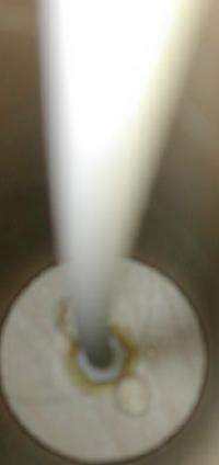
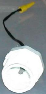 This photo shows the ejection
charge holder (3/4" PVC plug) with a Daveyfire match installed. To seal
the hole, I first inserted the leads, but left the head of the match hanging
out. I plopped some hot glue on the hole, and pulled the match through. This
made sure the channel was filled with glue. I then put a large fillet of hot
glue around the leads in the back.
This photo shows the ejection
charge holder (3/4" PVC plug) with a Daveyfire match installed. To seal
the hole, I first inserted the leads, but left the head of the match hanging
out. I plopped some hot glue on the hole, and pulled the match through. This
made sure the channel was filled with glue. I then put a large fillet of hot
glue around the leads in the back.
Prior to going to the launch site, I installed the G-Wiz, and the batteries, and re-verified the connections. I was going to take no chances and am separately powering the computer and the ejection charges, and will also use dual batteries on the latter. I found that I couldn't get the dual batteries assembly in once the altimeter was installed, so I had to remove and reinstall it after the batteries were mounted. Of course, the batteries were disconnected after continuity was verified.
The first flight was on an I211 and two G80s. I bought some dipped Daveyfires to light the G80's but decided that they were just too tight a fit. Since I am going with the dual battery configuration for ejection duties, I decided that I'd use Magnelite igniters instead. The G80s were fitted with aluminum clamp-on thrust rings and motor retainers so they don't fall out. I decided not to trust my nice thrust rings to mere masking tape.
At the launch site, I installed the shock cord with its Kevlar® sleeve. I used a humongous 24+" protector than I made from a car air-bag and a 66" chute that I got from Aerocon.
The flight was relatively 'slow and low'. Both airstart G80's lit, and there was some minor wobble at about that time. I suspect maybe the G80's may not have lit exactly at the same time. According to the G-Wiz, the flight reached 1734 feet. This may not have been accurate since I don't have pressurization holes in the bay (the G-Wiz staging and apogee deployment is accelerometer-based). Rocksim 6.05 says 2400 ft.
Recovery:
The 66" Aerocon chute deployed nicely and it came down nice and soft.
However, Murphy was at the site and the nose cone found the one rock-encrusted
access road at that end of the field. No real damage, but I left some Rustoleum
behind!
Summary:
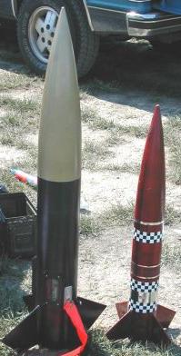
I love the looks of the Big Brute and like the results of the upscale. This
rocket allowed me to implement things I had been wanting to try, including air
starts, electronics mounted in the rocket's fin unit, and an ejection cannon
based on ¾" PVC fittings. I also tried out an adjustable nose weight
assembly. Everything worked as planned, and I am anxious to try out a J-motor!
 |
 |