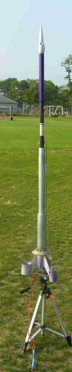
Scratch U.S.S. Fred G Sanford Original Design / Scratch Built
Scratch - U.S.S. Fred G Sanford {Scratch}
Contributed by David Mackiernan
| Manufacturer: | Scratch |
The following is the HTML
interpretation of David's PDF submission.
Please see the full PDF HERE (0.4M)
Constructing the
![]() For the EMRR BOX-O-Parts
Contest
For the EMRR BOX-O-Parts
Contest
Muddle through the Mess
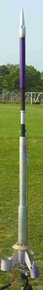
I started by separating body tubes in to groups that could be used as airframes and tubes that where crinkled,dinged, or dented.
This gave me an idea of the size and shape I could accomplish. My basic concept was for a long and tall rocket. Cluster power was a must. I LOVE clusters!

 The Nose Job
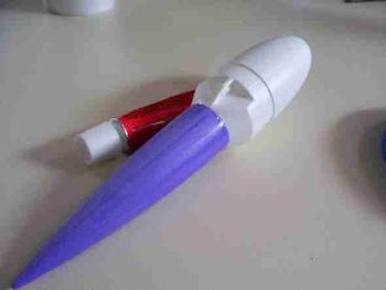
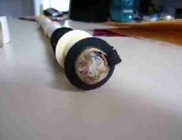
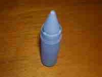
I messed around with Nose Cone possibilities. A rocket's nose really determines the "flavor" of the build. So with the cones I received I did some cutting, sanding and gluing. The results are photo #2. Looking a bit like a command module, perhaps windows looking out over a nose. Well I guess I'm building a Spacecraft of sorts.
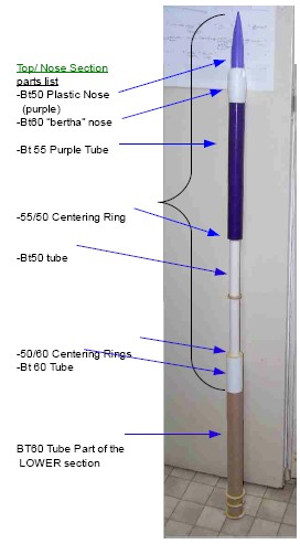
This is a "BERTHA" BT-60 plastic Nose Cone . Turned backwards. Purple BT-50 nose cone. Base is sawn off and glued to the bottom of the Bertha cone. Hopefully this will look something like a Starship cockpit.
 The Body Stack
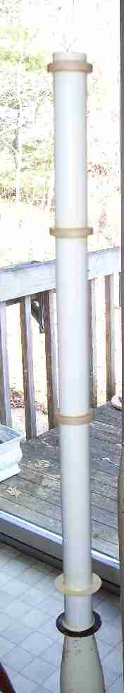
Go big or go Home.
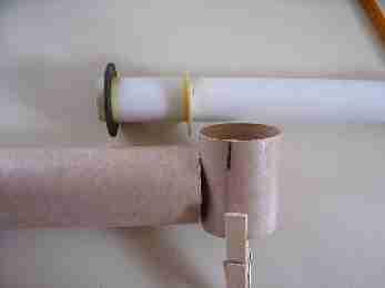
I took stock of all the possible body tubes I could use to go as tall as possible. This photo shows the Top and Middle sections test fit together.
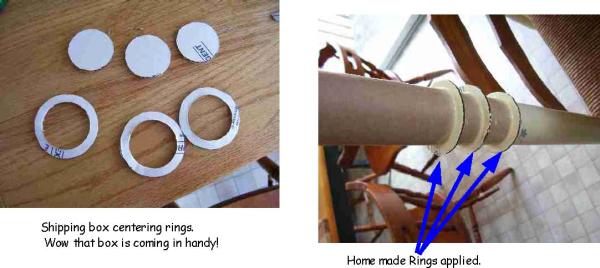
I sorted through the various centering rings in my stack of stuff and pieced together several sections of body tube to assemble the top stack.
This rocket is intended to separate for recovery at the point of the two different colored BT60 tubes. The mid section break allows the rocket to recover on two separate recovery devices. This was necessitated by the limited recovery options that came in my Box-0-stuff. (more on this later.)
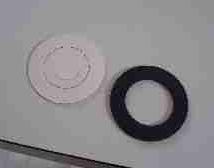 Some of the steps to build the top stack: Short one centering ring. So I modified one 20/60
ring to a 50/60 ring. Trace inner circle and cut out
Some of the steps to build the top stack: Short one centering ring. So I modified one 20/60
ring to a 50/60 ring. Trace inner circle and cut out
 Make a BT-60 adapter sleeve. Slice a section of BT60 tube to reduce diameter. Use the sliver that was
removed to brace the inside of the new inner sleeve and glue together. This makes the whole Top Section like one long
nose cone.
Make a BT-60 adapter sleeve. Slice a section of BT60 tube to reduce diameter. Use the sliver that was
removed to brace the inside of the new inner sleeve and glue together. This makes the whole Top Section like one long
nose cone.
More Top Section Assembly.
 The
BT50 Stack Middle Ring is Just for looks (pictured left)
The
BT50 Stack Middle Ring is Just for looks (pictured left)
Recovery would be the biggest issue. My Box-O-Stuff had One fat elastic cord. (below right)
I want to go BIG.... so, I split the cord in half Lengthwise, giving me two thinner elastics but still have the longest possible length. In this photo (below center) one half of this cord is pushed through a slot in the BT50 body tube. Tie a fat knot in the elastic and I'm off to the next step.
Next I have to fill the top BT50 section so it will separate at ejection. So I tore up some of the shipping box. Soaked the torn bits in water, then mixed the wet pulp with glue. Stuffed the glue/pulp mixture in the base of the tube to form a plug (above right). This method works well. You have to watch the moisture in the pulp mix so it does not warp the tube. This also takes a wile to dry.
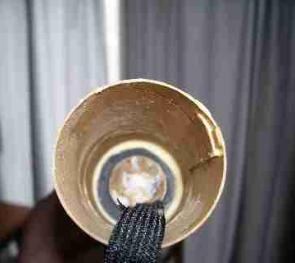 Looking into the bottom of the top stack. You see the BT60 adapter sleeve, the Elastic Cord and the bottom
of the BT50 centering ring and Glue/shredded box WAD.
Looking into the bottom of the top stack. You see the BT60 adapter sleeve, the Elastic Cord and the bottom
of the BT50 centering ring and Glue/shredded box WAD.
On to the Bottom section assembly.
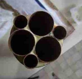
Well, for the lower section I have to connect some BT60 tube to some BT70.
No 60/70 centering rings in the Box-O-junk, so I whip out my trusty, rusty compass draw and cut some rings from the shipping box.
Motor Mount
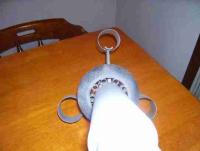
Coffee Cup With shred-obox soaking in water.
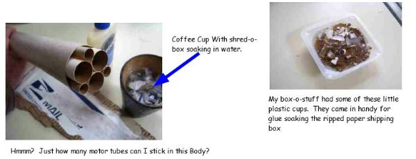
My Box-o-goodness did not contain any 18mm tube. So this one gets 24mm main motors (three of them). Just for kicks I added three 13mm mounts along side. Test fit the motor tubes. Then started shredding the Shipping box again. I use the shreds,soaked in water to soften them up, then ring them out and soak them in glue. Gluey shreds are then used to stuff the voids between the Motor tubes and Main body tube.
Motor mount continued.

Motor mount fillets drying (above right). In the "custom" motor mount drying apparatus a.k.a. a Dunki'n Donuts cup!
 A lovely Gluey mass of shredded box applied to the motor mount and lower body tube.
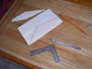
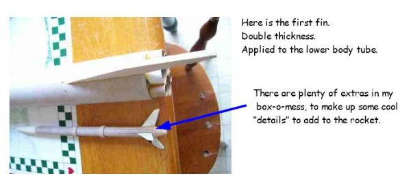
I better make some fins for this thing.
 Looks like I have a full set of pre-cut "Bertha" fins. (Actually I think I have at least one whole
bertha)
Looks like I have a full set of pre-cut "Bertha" fins. (Actually I think I have at least one whole
bertha)
But those Balsa fins may not be strong enough for a cluster. So I use a precut fin as a template to cut out some fins from the balsa sheet in the box. Then I laminate these fins so they are double thickness and hopefully quite strong.
Fins to the left, fins to the right.......
The lower section nearly complete.
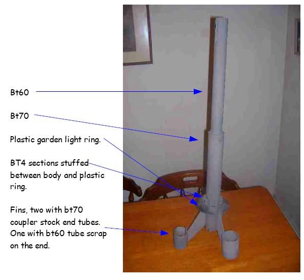
More lower section.
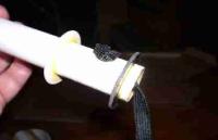
In these photos you can see the detail of the "Warp Ring"
Warp Ring is made up of a plastic garden light fixture. (I know this because I got some of my own parts back!)
The inside diameter of the plastic ring is much larger than the bt70 tube. So I pulled some small body tube that I believe is BT-4 and cut it to several short lengths. This BT-4 was squish-fit between the Plastic ring and the outside of the body tube. With the small tubes and plastic ring in place it was actually easy to slide the whole assembly (not yet glued together) down the BT70 body tube. Once I had everything where I wanted it I glued it all in place. With some patience and a few toothpicks of course.

Recovering from Recovery
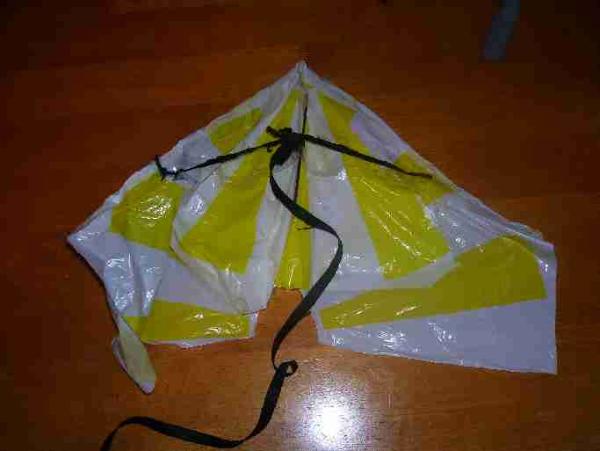
Official shop shot of the "parawing-gle"
My box-0-stuffing was kind of short on recovery options. It did have two plastic chutes. But only had shroud lines for one! I will bring the top half down on the regular 18 inch plastic chute that was in the box-o-lovely. But the lower section... that would be harder. Hmmmm? Streamer, boring! How about some sort of para wing?
O.K. this made me get creative. Some where in the TRF discussions it was asked if adding tape would be legal. Tape was o.k.ed so with ample amounts of scotch tape I fashioned this "Parawing-gle" type thing.
Parts for the Parawing-gle thing:
- One 24inch plastic chute. Sliced in half and then one half quartered.
- The quarter chute is used for the lower rudder type piece.
- Several Chopsticks are utilized as the leading edge and rudder stiffeners.
- That now famous thick black elastic cord was again sliced length-wise to make the rigging.
Many hours were spent on this. Mostly worrying time rather than working time. My greatest hope was that this would work at least as good as a streamer.
The big payoff!! 
Launched 07-06-08 From Cape Cod Space Center
Nothing like pushing that deadline!
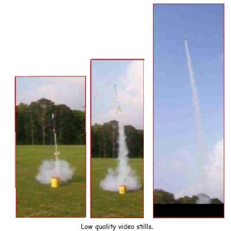
Nice liftoff, nice flight! Loaded in three C11-3's and three A10PT's. This rocket really needs "D" power but this was good for the small field we where on. Five of the six motors lit. All but one A-10.
O.k. recovery. Top half was just fine on a regular chute. Bottom half came in a bit fast on the Parawingle -thingle. Which became more like a big para wad of molten doom! But it did slow it down.
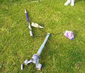
The aftermath. Minor damage. One "fin ring" slightly bent. One detail on that fin fell off
Overview and final thoughts.
This was a very cool contest. I would definitely try this again.
My only real wish is that we could add string (shroud line) if we needed it. But hey, no one said this was easy!

Over all Flight rating 4... it could use more power.
Overall Recovery rating 3. Needs proper chutes
But this is a far better performing rocket than I thought it would be. It will definitely fly again.
Things I will change, (with my own parts):
- Bigger Launch lugs 3/16"
- Better Parachutes
- Three "D" motors for a nice high flight.

 |
 |