| Manufacturer: | Scratch |

Brief:
Always a nice rocket to build is the V2. For mine I wanted to use 6"
tubing so I could build it around two 6"x19" Scotglas nose cones.
(The boat tail is a nose cone with the top missing.) My aim was to build a V2
capable of taking an L motor and dual deployment.
Construction:
The parts list:
- 2 19" V2 style Scotglas nose cones (1 for boat tail and 1 for nose cone)
- 4 Aluminum Honeycomb fins
- 1 21" x 6" PML phenolic tube for the airframe
- 1 5" x 6" PML coupler tube for the electronics bay
- 1 6" x 75mm coupler centering ring (to fit inside boat tail)
- 1 4" x 75mm centering ring
- 1 3" bulkhead (for recovery attachment inside nosecone)
- 2 6" bulkheads (for electronics bay)
- 2 29mm x 2" tubes (for recessed ejection charge housing)
- 1 54mm x 4" tube (for recessed recovery attachment)
- 1 54mm x 1.5" coupler tube (end cap to 54mm x 4" tube)
- 2 5" long threaded rod (through electronics bay)
- 1 18" x 75mm phenolic motor tube
- 4 8mm thick eyebolts for recovery attachment
- 1 U-bolt for recovery attachment
- 1 Aero Pack 75mm motor retainer
- 4 3mm x 10mm headless bolts (to act as reinforcement pins)
- various nuts and washers
- 5 pounds lead shot for nose weight
- Fiberglass and CarbonFibre cloth to lay-up phenolic airframe
- enough 2-part foam to fill the boat tail section
- 10mm thick wooden edging to make alloy fin edges
- 2 25' x 24mm tubular nylon.
- House-Of-Color primer, white and black paint
I designed the V2 to recover according to the standard 3 piece recovery model (Nosecone, Airframe, Boat tail). Peter Alway's ROTW was essential in getting the specific measurements to scale. Once all the measurements were done I entered the data into RockSim to establish a set of components from which the V2 would be built. It quickly became clear that space in the aft recovery bay would be limited since the boat tail shoulder protrudes 4" into the bay. Plus the L800 motor casing protrudes a further inch into the bay. A quick measurement of my electronics requirements (namely the height of the PCBs plus room for the wiring) and I had the minimum height of my electronics bay to provide the maximum amount of room in the aft recovery section. To further increase the amount of available space in the aft compartment, the ejection charges would be recessed into the electronics bay. Plus the recovery harness attachment point to the airframe section would also be recessed using a 54mm tube that ran through the center of the electronics bay to allow the 8mm eyebolt to be attached to the underside of the forward bulkplate of the electronics bay. Thus the aft recovery harness would run through 54mm tube (and through the center of the electronics bay) down to the eyebolts on the boat tail. Using this method of hide and seek with the ejection charges and recovery eyebolt, I was left with a 2" x 6" space to house my aft recovery harness.
The build was not easy nor was it hard. It was complex owing to the requirement to maximize recovery compartment space and support for 75mm motors.
For the 4 distinctive V2 fins I used 10mm aluminum honeycomb which I was able to cut to size with a hacksaw after drawing the fin shape on the material using a paper cutout as a template. The honeycomb cuts easily but resists the blade enough to make this difficult. Once cut the honeycomb requires the visible edges to be profiled using some other material which can be glued along the edges of the fins, filled and sanded to provide a finished fin. I used 10mm wood edging from my local DIY store. Imagine a 1/2 cylinder shape, i.e., one flat side and a dome. This worked well to give a rounded edge on all sides except for the root edge. Any gaps between the honeycomb and the wood edging were filled with epoxy and later sanded smooth. I have used honeycomb a couple of times now and feel that although it does not save much build time because of required edging and filling, it more than makes up for this by giving the lightest and strongest fins you will ever make. Truly remarkable stuff.
The V2 has a boat tail which was created for my build using a second fiberglass nosecone identical to the first with the tip cut off. As I was going to be flying this on a 75mm motor, I needed the opening at the bottom to be at least 75mm to fit the motor tube. This width was further increased by the need to house an Aero Pack 75mm motor retainer, which is the one where you have threaded inserts to drill into your aft centering ring. With this in mind, it became clear that the width would need to be 4" to allow for a 4" x 75mm centering ring to be used to mount the motor retainer.
The point on the nosecone to cut was established by placing the 4" centering ring inside the 'clear' nosecone (I did not have the aft nosecone gel coated) and then marking the position at the bottom of the ring as it rested in the tip of the nosecone.
Once cut, the boat tail needed slots to pass the 10mm wide fin tabs to allow mounting to the motor tube. I used my trusty Dremel to carefully cut the slots leaving a 1/2" area at the bottom of the boat tail.
The aft centering ring was carefully drilled to hold the threaded inserts for the Aero Pack motor retainer. Once drilled, the inserts were glued into place. You want to avoid getting epoxy on the inside threads so use tape, blue tack, grease, etc. in or over the threads. The centering ring was then glued into place at the bottom of the boat tail along with the 75mm motor mount.
The 4 fins were epoxied to the motor tube. To reinforce the bond with the motor mount, an internal fin-to-fin layup of carbon fibre was performed between the 4 fins, which was very tricky to do this as there is very little room.
I decided to foam the remaining space inside the boat tail. This would really seal the fins and motor mount to the boat tail. The usual 2-part expanding foam was used for this. I had also decided to use the length of the boat tail to house the antenna to my Marshal radio transmitter so a plastic tube was inserted into the boat tail with the aim of pouring the foam round the tube to leave a nice channel for the antenna to run the length of the boat tail. However, during the pour I discovered that the foam was eating the plastic tube and as a result the tube was unusable. Fortunately, once the foam set I was able to use a long hollow brass tube to "drill" out a channel that ran from the top to the bottom of the boat tail. I then placed a new plastic tube down this channel to house the antenna.
The centering ring at the top of the boat tail needed to fit inside the shoulder. Hence a 6"x75mm coupler centering ring was custom made for me by Rebel Rocketry. Two 8mm holes were drilled to hold the large eyebolts which were epoxied in place with appropriate washers and nuts on the underside. Additionally, I drilled a 1/2" hole centered over the plastic tube (antenna channel) to fit the body of the Marshal radio transmitter. The transmitter would be recessed into the centering ring and boat tail. (I used a 18mm tube with the end sealed but with a hole for the antenna to act as a housing for the transmitter.) The centering ring was epoxied in place with the motor tube protruding 1/8" or so above the top of the centering ring. Epoxy was applied round the top of the motor tube where it touched the centering ring to give a solid bond. Thickened epoxy was used to fill any gaps between the centering ring and the boat tail. Once dried, I drilled four 3mm holes to allow 10mm long headless bolts to pin the centering ring to the boat tail. This would prevent any slippage or other movement due to the recovery stresses on the boat tail centering ring.
Fin fillets were applied using thickened West Systems epoxy. An interesting affect was observed when applying the fillets. The resin reacted to the 2-part foam in the cracks between the fin wall and the boat tail causing large bubbles to form--not many of them but they were big! There was nothing to do for this except wait until the resin cured and then file down the raised fillet and fill the exposed holes. This was a real pain but with some patience all was well in the end.
The airframe section was a single 20" piece of phenolic tubing. Since most of the length of the airframe would have a double thickness (owing to the shoulders of the nose cone, boat tail, and the electronics bay), I decided upon a single layup of 200g carbon fibre cloth and fiberglass as reinforcement. I used my trusty Foodsaver to vacuum bag the part with couplers inside to keep the vacuum from crushing the tube. End caps were just coupler and normal bulkplates. Easy peasy.
The electronics bay was more involved than complicated. Since this bay was going to be epoxied to the inside of the airframe, I used bulkheads instead of coupler bulkheads. The aft bulkhead was drilled with a central 54mm hole and two opposite 29mm holes. Additionally, two holes were drilled to allow blind T-nuts to be attached to the underside of the bulkhead to hold two short pieces of threaded rod which would connect the forward with the aft bulkheads and provide for strong recovery mount points as well as seal the bay from the ejection charge gasses. Once the 29 and 54mm holes were drilled, the short (1.5") pieces of 29mm tubing were fit and epoxied into their holes with the tubes protruding into the electronics bay, along with a longer 54mm tube, which ran the full length of the electronics bay. The forward bay bulkhead required holes to be drilled to allow the threaded rods to protrude above the bay and enable wing nuts to be used. Additional holes were drilled to enable the forward bulkhead to use a U-bolt to attach the forward recovery harness as well as an 8mm eyebolt to the underside of the bulkhead centered over the 54mm opening. Finally, a 1.5" section of 54mm coupler was attached to the forward bulkhead centered over the 54mm tube and eyebolt and pointing down into the electronics bay as an inside sleeve to the 54mm tube. This was finished with some instant heat gasket around the outside of the sleeve tube to provide a gas proof seal. The result of all of this was to allow for the ejection charges to be recessed into the electronics bay and to enable the aft recovery hard point to be out of the way of the L motor plus providing a little be extra room for the aft recovery harness.
The nose cone required a bulkhead to mount the recovery harness eyebolt and enough lead shot to bring the center of gravity forward. This turned out to be 4.5lbs mixed with West Systems epoxy and poured into the nosecone. I used a long 8mm eyebolt with an extra nut and washer to enable the resin and lead mixture to really grip the eyebolt/bulkhead assembly. Once poured, the nose cone was suspended in water to cool the resin and prevent deformation of the nosecone as the exothermic reaction is quite fierce. Once cured the nose cone was ready.
Finishing:
Originally I wanted to use the camouflage color scheme for the V2 but I did not
manage to get the colors sorted for my sprayer. I decided upon the black and
white roll pattern instead. All paints were House of Kolor brand auto paints.
Prior to painting, I first applied UV Smooth Prime to the composite airframe
section. This filled the weave left by the fabric. After sanding with my palm
sander, it left a nice smooth surface ready for priming. I sanded all flat
surfaces using my palm sander.
The primer sprays on bright green and really sticks to composite surfaces. I put down about 4 coats of primer before spraying the entire rocket black. A top coat was applied before being left to dry.
I purchased some transparent frisk from an artist supply company. This stuff is great for masking as it is very low tack but so thin that you can cut it in place and comes up very easily. The painted edges look very sharp.
Once masked (and this took a couple of hours to do), I sprayed white to finish the roll pattern. The frisk was removed then a final top coat of gloss sprayed.
It was a lot of work in the end but the results looked good. I would still like to use the camo colors at some point.
No decals were used apart from a small white vinyl East Anglia Rocketry Society (EARS) logo.
Flight:
The prep for the first flight consisted of two 25ft sections of 24mm tubular
nylon, a SkyAngle 44" chute (a bit small for this rocket but I wanted to
bring it down fast), and 4 shear pins to keep the nosecone on at apogee.
The electronics consisted of 1 MiniAlt, 1 RDAS, and 1 BlackSky timer. The timer would be used to control an ARRD which would be used as a backup in the event that the shear pins did not hold the nosecone. The ARRD was attached to the forward bulkhead by using one of the threaded rods to act as a threaded post for the ARRD, which has a 6mm threaded hole.
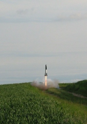
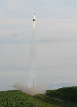
The launch pictures were taken by Nial Oswald.
The RDAS and MiniAlt controlled the primary and backup drogue and main ejection charges (2 x 1gm aft and 2 x 4gm forward). I did not install any switches so twisting bare wires wrapped with electrical tape was used to arm the electronics. The timer requires a screwdriver to arm it, so I drilled a hole pattern to allow external arming and viewing of the LEDs.
The recovery harness just fit in the aft section with no drogue chute. The nosecone had ample space to hold the forward recovery harness and chute.
First flight was on a Cesaroni Pro75 L800 PU classic reload using a 75mm Aerotech motor casing. The reload was a snap to build and before long I was ready to go to the pad.
A quick 5 count, a pause for the motor came up to pressure, and the rocket blasted off the pad. The lift off was a very satisfying roar with sustained thrust to push the 25lb rocket quickly to 8700 feet but not too fast to miss seeing the rocket climb. The flame plume was as long as the rocket and looked great.
Recovery:
The flight on the L800 was very nice in the early evening sunshine. At apogee,
the rocket was out of sight but a few seconds later you could see a bright
orange and yellow chute. Rats! The chute deployed at apogee despite the shear
pins and ARRD. It was came down fast on the relatively small chute and landed
about 1/2 mile down range in the crops. Initial estimates of where exactly it
landed were short of its final resting place. The signal on the tracking
receiver was quite weak but enough to gain a direction. After about 300 meters,
it started beeping louder and a short time later I was standing over the rocket
in the crops. The two altimeters where beeping out altitudes over 8700 feet.
Upon inspection the quick descent slightly damaged one of the alloy composite
fins. Not enough to cause concern but it may need a bit of attention before its
next launch.
My best guess on the failure to retain the nosecone is:
- Too much BP was used in appogee ejection charge causing a violent separation which resulted in the shear pins -- shearing. This force was also too much for the ARRD to cope with so out came the main chute.
- The shear pins were tool small.
Summary:
Great fun in all. A bit more care on the amount of BP with bigger shear pins next time.
Other Reviews
- Scratch V2 By Kevin McLaughlin
( Contributed - by Kevin Mclaughlin - 11/15/02) Brief: Scale model of infamous German WWII V-2 in 3.9" dia x 37" tall scale with 29MM motor mount that can handle up to 29 x 240 hardware. Empty weight of this rocket is 53 oz including nose cone weights for a G64 RMS. VCP is at 12.7" and CG at 16.8" fully loaded with G64 RMS, tubular nylon shock chord and 45" ...
- Scratch V2 By Brian Kain
( Contributed - by Brian Kain) Brief: Scratch 4" V-2. Flies on H through J 38mm motors. The nose has interchangeable weights so the rocket can be properly weighted for any given motor. I use a silk 36" chute I got from AEROCON. Construction: 1- 4" dia LOC body tube 8.5" long. Glassed with 6oz cloth and 30 min epoxy. This rocket has no payload section ...
 |
 |