| Manufacturer: | Scratch |
I love the Estes Yellow Jacket. I’ve built 2 originals, and many upscales and downscales. I’ve taken to identifying the YJ’s in my fleet by the number and size of the engines, so my 2.6-inch upscale was the YJ-324, indicating a triple cluster mount of 24mm motors. The name for this rocket means that a cluster of two 18mm mounts are installed. This was my very first cluster rocket, and after 20 sweet flights on C6-5’s and C6-7’s she’s still going strong.
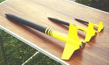 |
Pictured here is the YJ-218, an original Yellow Jacket in the middle, and a 13mm downscale, the YJ-113. |
Materials:
- PNC-60 Nose Cone — not the Big Bertha or Mean Machine type, it’s 4.75-inches long (not including shoulder).
- BT-60 Body Tube — true scale is 21.3-inches long, but mine is 24.75-inches to compensate for the too-short nose cone.
- TC-60 body tube couplers as needed, possibly one or two.
- BT-20 Body Tubes — you’ll need 2, each around 3-inches long for the motor mounts.
- Cardboard for the centering rings — I used cereal box cardboard as described below.
- Balsa fin stock — 1/8-inch thick.
- Launch lugs — 3/16-inches or use rail buttons (mine has both)
- Shock Cord — at least 36-inches of 1/4-inch elastic, more is better.
Also:
- Elmer’s Fill’n’Finish
- Yellow wood glue
- Thin CA
Construction:
Jim Z’s site has the original Yellow Jacket plans here, and except as noted the construction is the same.
What follows aren’t complete construction steps, just highlights for the methods I used here and there.
The centering rings are the most involved part of construction. Start by laying out the diameter of the first centering ring on your sheet of cardboard. Next, bisect the circle into four quadrants (make an ‘X’ centered in the circle). Holding the two BT-20’s together, trace around them so that they are centered along one axis and the other axis splits them. There are more precise ways of doing the layout, but the semi-freehand method is what I used, and it works fine.
Use an X-acto knife to carefully cut out the inside holes. Test fit the motor mounts and sand the holes as needed. The main thing is to not compress the motor tubes, or you’ll have trouble getting the motors in or out.
Once the inner holes are cut, use scissors to cut out the outer diameter. Trim to fit the body tube. Now use this first centering ring as a template to make 3 more.
When all are cut and fit, glue them together into pairs so you have two double-thick rings. You can use yellow glue or thin CA. Once dry, use yellow glue to attach them to the motor mount tubes, making sure the tubes ends are even and they’re not twisted along their length. I usually leave the front ring about 1/4-inch back to make room for a good glue fillet around the top, and the back ring should be glued on about 1/2-inch from the end.
Print the fin template from the original plans, then enlarge it 168% on a copier for the correct sizing. The fins are simply 1/8-inch balsa, sanded and sealed with Fill’n’Finish. Airfoil if you want, I just rounded the leading and trailing edges. After they’re attached to the body tube with yellow glue, soak the fins with thin CA for extra strength. You can add tabs to the root edges and make the fins through the wall, but I’ve had not had any problems with surface mount.
One of the couplers is used in front of the motor mount to strengthen the body tube. This area just forward of the fins takes a tremendous amount of stress during flight, and a coupler here greatly reduces the possibility of tube crimps during the boost phase and upon landing.
I used the standard Estes ‘paper sandwich’ shock cord mount, and it’s holding up fine. There’s plenty of room in the body tube for wadding and lots of shock cord, so be generous with both. This rocket is light enough to come down on a 4" X 40" streamer, but we recover on soft grass so if your field is harder ground you’ll want to use a 15" or 18" chute.
If you don’t make your own decals, Tango Papa can make enlarged versions for you at a reasonable cost. Or you can forego the decals and use auto pinstriping tape for the stripes. For the YJ-218, the bottom 13.4-inches is painted yellow.
I did not install motor retention. What I do is insert the motors, then use a wrap of masking tape around both the motor casings and the motor mount tubes. I’ve never had a motor kick using this method with black powder motors.
Final ready-to-fly weight, excluding engines, is around 5 ounces.
Flight:
C6-7’s are the perfect motor for this rocket, but C6-5’s can be used without sacrificing much altitude.
I fly a lot of clusters, and out of many, many flights I’ve had exactly 2 motors fail to ignite. The key to success is attention to detail. Make sure the motor nozzles aren’t clogged with excess clay before installing them. Use igniters in good condition, with plenty of pyrogen on the ends. Carefully twist together one lead from each igniter, then twist together the other pair before attaching the clips from the launch controller. If you use clip-whips instead, solder the connections for reliability. It’s also very important to make sure that the battery you’re using has enough oomph to fire all of the igniters at once because a standard Estes controller will not do it reliably.
Related Products
 |
 |