Scratch Zodiac Original Design / Scratch Built
Scratch - Zodiac {Scratch}
Contributed by Christopher Rhodes
| Manufacturer: | Scratch |
Brief:
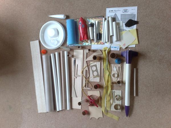
My Box o’Parts build is the first scratch built rocket I’ve made and so upon seeing the random assortment
of parts and “junk” I received it looked like quite a daunting challenge. With it being my first scratch
built rocket I decided on a relatively standard design so as not to confuse myself too much but then to spice it up
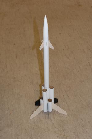
with a considerable number of fins. The final product was a twelve finned, parachute recovery rocket with six small
tubes around its base, I flew it off of one D motor but potentially seven could be used. I named the rocket Zodiac
after its twelve fins.
Construction:
- 1x 24” Main Body tube (24mm diameter)
- 3x 6” Tube (24mm diameter)
- 3x 4” Tube (24mm diameter)
- 1x 5” Cone (24mm base diameter)
- 1x 22mm Body tube Connector
- 22mm Engine stop
- Thin balsa sheet
- 3x plastic fins
- 2x launch lugs (one small, one large diameter)
- 10”x10” plastic sheet
- A4 piece of Card
- 3x Sticky Labels
- 18” Elastic Cord
- 3x 20” shock cord
I started the build by cutting one end off of the body tube connector and then cutting a wedge out of the side of it to allow the connector to be glued up into the cone. This was done by squeezing the top of the connector and then using plastic cement to create a nosecone with a connector which would both allow the cone to be held sturdily on top of the rocket and to allow an elastic cord to be attached at a later stage.
The six smaller tubes which would be glued around the base of the main body tube were then cut from longer tubes in the box o’parts, once this was done each 4” tube was glued to a 6” tube with PVA, ensuring the bases were level. These were left to dry and then the pairs glued onto the base of the rocket in an alternating 6” tube, 4” tube fashion. An engine block was also glued inside the main body tube just far enough to allow a D motor to protrude from the body tube by 6mm.
To complete the base of the rocket 3 of the plastic fins from the box were glued in the gaps between the tubes at intervals with 3 larger fins cut from balsa. The balsa fins were designed so as to start at the same level as the plastic fins and the recede back to the same height as the plastic fins to allow all 6 base fins to support the rocket when standing. After cutting the fins from the balsa their edges were sanded and the leading edge rounded to increase aerodynamics. The nature of the gaps between the smaller tubes made it easy to ensure correct fin alignment but the fins were attached one at a time, aligned and allowed to dry to ensure all of the fins were attached correctly. The two launch lugs were then glued on the inside of the smaller tubes next to the main body tube, making sure they were not in line with any of the fins at the top.
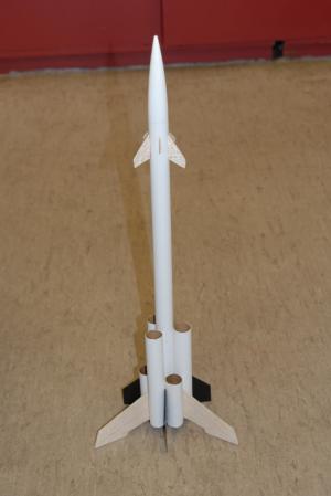
 Once complete this gave a very sturdy rocket but looked a bit bare towards the top as the main
focus of the rocket was the base. To add more detail another 6 fins were cut from balsa to match the pattern round the
base. These were two different shapes and were glued ½” from the top of the body tube in line with the tubes
around the base, again in an alternating fashion. To help align the smaller fins, a line was drawn up from where the
gap between each of the smaller tubes was and then each fin glued separately.
Once complete this gave a very sturdy rocket but looked a bit bare towards the top as the main
focus of the rocket was the base. To add more detail another 6 fins were cut from balsa to match the pattern round the
base. These were two different shapes and were glued ½” from the top of the body tube in line with the tubes
around the base, again in an alternating fashion. To help align the smaller fins, a line was drawn up from where the
gap between each of the smaller tubes was and then each fin glued separately.
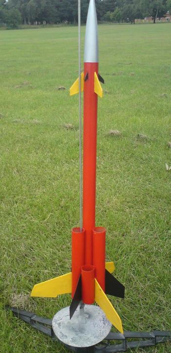
At this stage the nosecone was then sprayed silver and the main body red, the fins were protected with masking tape during spraying then the balsa fins painted yellow and the plastic fins painted black, the fins at the top were painted to match the colour of the larger fins below them.
The parachute was then constructed from the plastic sheet by strengthening each of the six corners with a piece of sticky label and then piercing holes in them. Shroud line was then passed through each hole and stuck down with more sticky label. Each piece of shroud line passed through two adjacent holes and the loops were then collected at the base where they were glued together. The elastic was then glued to a folded piece of card and glued into the main body tube. The shroud lines were then tied onto the elastic and the elastic tied onto the nose cone connector.
With the rocket finished I checked the paint work and touched up the fins, Zodiac was ready to fly.
Flight:
My rocket was designed for a D motor however this was probably not the best idea as the weight of the rocket was low
enough for a B to be sufficient. However with a small parachute I hoped recovery wouldn’t be too difficult.
The first flight was in what seemed reasonably still conditions and Zodiac flew perfectly off the pad on a D12-7, however, half way through flight a huge gust of wind took Zodiac from its straight flight and sent it at an angle. The parachute still deployed at apogee but the rocket was already away from the launch site. The rocket then drifted into a bunch of trees where it got stuck at the top of a tree, just out of reach. Unfortunately it could not be flown again.
Summary:
The build itself went fantastically and the flight of the rocket was spot on, however on a D motor the rocket is just
too light and unless you have a very large area to fly it is quite likely that the rocket will be unrecoverable even on
a small parachute.
 |
 |