| Construction Rating: | starstarstarstarstar_border |
| Flight Rating: | starstarstarstarstar_border |
| Overall Rating: | starstarstarstarstar_border |
| Diameter: | 0.91 inches |
| Length: | 18.10 inches |
| Manufacturer: | Semroc  |
| Skill Level: | 2 |
| Style: | Multi-Stage |
Brief:
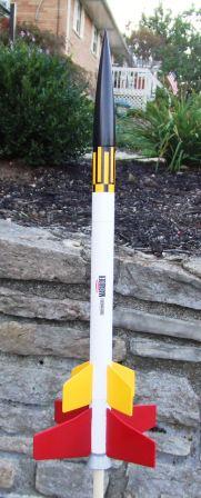
This is a Retro Repro based upon the 1969 Centuri Marauder. It's a two stage model featuring dual-lock staging (aka
Pass-Port Staging). It's a nice looking two-stage payloader (tiny) and a decent value for under $20 retail.
Construction:
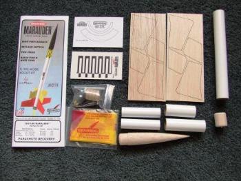
Components are excellent quality and include:
- Balsa nose cone
- Series 8 body tubes (booster, main, payload bay)
- Laser cut balsa fins (4+4)
- Balsa bulkhead
- BT-20 motor tubes (2)
- Centering rings, motor blocks
- Tube coupler
- Cardstock shrouds (2)
- 1/8" launch lug
- Plastic chute (12")
- Kevlar®/elastic shock cord
- Waterslide decals
 Instructions are clearly written and illustrated, typical for Semroc. Since I'd had no prior
experience with the Pass Port staging system, I had to actually pay attention to these instructions, and recommend
others do so as well. It's about a skill level 2 kit, and I'd guess that construction wound up around 2 hours plus
finishing, though i was building this along with 6 other kits at the same time, so tagging time to specific ones was an
arbitrary guess.
Instructions are clearly written and illustrated, typical for Semroc. Since I'd had no prior
experience with the Pass Port staging system, I had to actually pay attention to these instructions, and recommend
others do so as well. It's about a skill level 2 kit, and I'd guess that construction wound up around 2 hours plus
finishing, though i was building this along with 6 other kits at the same time, so tagging time to specific ones was an
arbitrary guess.
 Beginning with the booster, I put the motor block in what
winds up being the aft end of the tube, completely backwards from the norm. An external tube coupler (pre-punched for
vent, nice feature!) goes on the other end, and a pair of centering rings completes the booster motor tube assembly.
I'll admit I was questioning myself along the way, wondering if I wasn't really building the sustainer motor tube
instead.
Beginning with the booster, I put the motor block in what
winds up being the aft end of the tube, completely backwards from the norm. An external tube coupler (pre-punched for
vent, nice feature!) goes on the other end, and a pair of centering rings completes the booster motor tube assembly.
I'll admit I was questioning myself along the way, wondering if I wasn't really building the sustainer motor tube
instead.
Next the booster and sustainer body tubes are marked for 4-fin configuration using a template on the instruction sheet. The booster motor tube assembly is then inserted into the booster body tube, leaving about 3/4" exposed out the aft end. There are two shrouds that go on this end, and I suspect if you made and aligned everything perfectly, the aft most shroud would be flush to the motor tube, but in my case the motor tube extends about 1/8" beyond the shroud.
The sustainer motor tube gets a block in the forward end (the normal way), and a pair of centering rings, the
forward one also serving as anchor for the Kevlar®
shock cord.
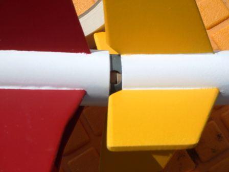
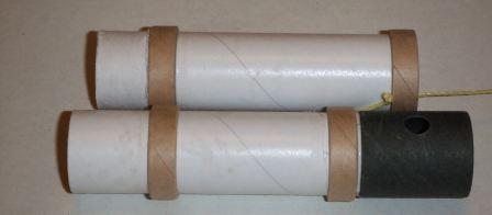
The sustainer motor tube should slide into the open coupler sticking out the booster, but in my case the fit was a bit too tight. In addition to sanding the ID of the coupler a bit, I also had to peel off a layer of wrap from the outside of the sustainer motor tube. See photo for how they fit together--it's pretty slick. The booster motor is inserted from the front end, and needs good tape friction fit. The sustainer motor is loaded like normal, from the aft end. The two plug together, joined by the external coupler.
Booster and sustainer each get 4 fins tacked on. They are close enough together I'd have preferred to see an interlocking design, but this looks OK.
There is a tiny payload bay, a whopping 3", but between the nose cone shoulder and bulkhead, there's only about 2 effective inches, so good luck fitting in that altimeter or video camera. Maybe a small insect...
Attaching the launch lug and screw eye for the bulkhead wraps up construction.
Finishing:
Finishing is pretty simple. After a couple primer coats, I went with 2 coats of gloss white. I then masked off for
the fins, with the booster getting red and the sustainer yellow. I also painted the forward section of the sustainer
yellow to match the cover art--the black roll bar pattern is printed over clear, but shown against a yellow background.
The nose cone was painted black, and the shrouds had painted black rather than try to mask and spray.
Construction Rating: 4 out of 5
Flight:
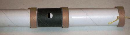
Flight prep is a bit unusual on this one, compared to the typical two-stager. The booster motor goes in from the
forward end of the tube, not aft, so needs a little tape for friction fit on the delay end, not the nozzle end. The
sustainer motor loads normally, also friction fit. If everything lines up correctly, the sustainer motor slides down
into the coupler holding the booster motor in place during boost. As shown in the photo, though, in my case there was
about a 1/4" gap in there somehow, indicating that either the directions are off a bit or one of my thrust rings
is not properly placed, which is hard to blow considering they are both mounted flush to tube ends.
I wound up sawing off a bit from the end of a B6-0 and slipped a B6-4 in the sustainer, figuring with winds around 10 mph I'd be in for a long recovery trek. Staging worked flawlessly, though there was a little bit of a tip-off so the sustainer went on a slightly angled trajectory.
Recovery:
The booster tumbled gently down and was recovered near the pad. The 12" plastic chute on the sustainer is fine,
sized right for grass fields. The only sign of damage was some singing of the fins, and residue buildup in the chamber
where the two stages mate up that makes it a bit too tight for a second flight without sanding it out and cleaning.
Flight Rating: 4 out of 5
Summary:
Overall, I do like the dual-lock staging, though am a bit concerned about how well it holds up over time. I'm also a
bit perplexed at the fit problem between the two stages and will have to figure out what went wrong there. Hacking off
motor ends is not something I routinely want to do (especially if flying with a C6-0), so it will probably just fly
with a gap exposed in the future.
Overall Rating: 4 out of 5
 |
 |
Flights
|
|
|
|
P.S.L. (October 13, 2009)