Sheri's Hot Rockets Little Joe II
Sheri's Hot Rockets - Little Joe II {Kit}
Contributed by Robert Koenn
| Construction Rating: | starstarstarstarstar_border |
| Flight Rating: | starstarstarstarstar_border |
| Overall Rating: | starstarstarstarstar_border |
| Manufacturer: | Sheri's Hot Rockets  |
Brief:
I think the Apollo Little Joe 2 is probably my favorite rocket of all time. I am not sure why but I liked the appearance of it back in the late '60s when I purchased my first Estes kit during my high school days. I think it is the Apollo capsule and launch escape system (LES) parked on top of a stubby, brute force rocket of very basic design. The actual vehicle was a conglomeration of solid motors assembled in an airframe for accelerating the Apollo/LES combo to simulate actual Saturn flight conditions for testing the LES. And personally I like the early clean versions of the rocket better than the later much more elaborate versions. I recently built the Semroc small version and decided it was time to pull out the large scale kit that I had purchased from Sheri a few months back but hadn't started yet. This kit is definitely a test of a modeler's building skills and that was part of my reason for putting off building it. But it looked to be a great scale model and impressive flying model of the Little Joe.
Construction:
The rocket came from Sheri in a cardboard box. This kit has a large tube and the various parts were packed loosely in the box. Instructions were a copied multi-page manual with pictures of the various phases of construction. Parts include:
- Large heavy duty, carpet tube type body tube
- 29 mm engine tube
- Plywood engine centering rings
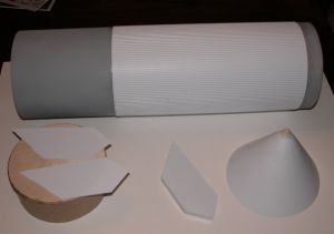
- Plywood capsule base disk
- Sheet of styrene for the fins and capsule
- Corrugated plastic body tube wrap (2 pieces)
- Plastruct round tubing for escape tower
- Plastruct small square trim strips
- Large screw eye and locking nut
- Wooden dowel for escape tower
- PVC launch lugs
- Wooden launch lug standoffs
- Small wooden dowel for capsule tip
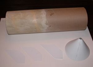
Looking through the box of parts my first impression was this was going to be a significant construction task, probably more than I had assumed when I purchased the kit but still manageable. Everything involved in construction was going to require building, there were really no pre-made or molded parts other than the corrugated wrap and launch lugs. I also immediately noted the body tube which appeared similar to the tubing you see used for carpet rolls. The tube had a deep spiral groove, the surface was fuzzy and very rough, and the tube was very heavy which could be considered as much a plus as a minus. I suppose I was rather unimpressed by this and realized this tube was going to take some real work to obtain a smooth surface finish. I actually put off building this model for some months after opening it once I discovered this during my initial inspection.
My first step was to assemble the engine mount. The kit includes a length of 29mm tube for the engine. The tube was longer than I felt necessary so I cut it down to about 12 inches in length. I then epoxied the plywood centering rings about an inch from each end. After these had cured, I drilled a small hole in the forward centering ring and installed the screw eye and nut for the recovery system epoxying the nut after threading it on to prevent the possibility it would come loose in the future. I also attached a 15 inch long piece of braided wire cable I had bought at the hardware store for attaching the recovery system later. I used a wire crimp to secure the braided wire through the screw eye.
Next up was cutting the main rocket body tube piece from the cardboard tube. The cardboard tube was a single piece and the body tube and nose cone coupler need to be cut from it. Because of the thickness of the tube the cutting was somewhat difficult. A saw was recommended, but I simply used a heavy duty X-Acto knife with a fresh blade. It took a number of rotations around the tube with the knife but I managed a good clean cut. I then epoxied the engine mount into the tube so that the engine tube was flush with the aft end of the body tube. I finished by applying epoxy fillets around the aft centering ring.
When this was completed I marked off roughly where the forward edge of the corrugated plastic wrap would come to on the body tube. I performed my finishing on the body tube only to a point slightly below where the corrugated wrap would end which saved a significant amount of work finishing the tube. I filled the very deep and wide spiral groove with Elmer's squeeze putty and sanded it smooth after it had hardened. I then applied two coats of Elmer's Fill 'n' Finish mixed in water to seal the tube. Between each coat I sanded the rough tube to a smooth finish. I followed this up with two coats of Coverite balsa prep sanding between coats. Finally I painted the tube with three coats of Rustoleum gray auto primer sanding between coats. This completed the tube prep and I had a fairly good smooth finish on the upper portion of the tube.
Next up was applying the corrugated plastic wrap to the body. Because of the large diameter of the body tube, the wrap comes in two pieces. They need to be joined with a thin strip of plastic that is supplied with the kit. It is a fairly simple task which I performed on my extremely flat kitchen counter. I used Tenex liquid plastic cement and applied a coating to both sides of the corrugated wraps and then to the plastic coupling strip. This does need to be done very quickly since the liquid glue evaporates rapidly. The slightly soft plastic strip is lapped across the two corrugated wraps to join them. This worked very well and once the glue had cured, the corrugated wrap was a single piece. The next step to prepare for gluing the wrap to the tube was to tightly wrap it around the tube and mark where the joint will be. The corrugated wrap is then cut lengthwise to make it the correct diameter for the body tube. This is fairly simple since the corrugations provide a perfect marking line for the cut. Sheri recommends attaching the wrap to the body tube with CA glue. I decided, based on doing plastic wraps previously, to use spray contact cement. I masked off the forward end of the body tube with paper to protect it from contact cement overspray and sprayed the cement onto the lower tube. I then sprayed the cement onto the back of the corrugated wrap. I had also penciled a lengthwise line on the body tube to line up the wrap with prior to spraying the contact cement on. I very carefully lined up one edge of the wrap to this line and working from that edge around tightly pressed the wrap onto the body tube. This needs to be done very carefully to get the correct alignment and because buckling or misalignment of the wrap would be very difficult if not impossible to fix. After the wrap is on the body tube I carefully glued down all the edges with medium thick CA glue. The final step is to use CA glue to attach some small strips of square plastruct around the top and bottom edge of the wrap. This provides a nice clean edge for the wrap.
 In parallel with the body tube prep, I had also started working on the fins. The fins are built up using 0.030 inch thick styrene. I cut the fin template from the instruction sheet and penciled the template onto the styrene for all eight fins. Sheri recommended that a knife be used to scribe the styrene and then breaking the fins from the styrene. I found that a good pair of scissors worked fine and cut all my templates and strips from the styrene with the scissors. After the fin panels are cut, it was necessary to cut some strips of styrene 1/4 inch wide. These are used for the fin edges. The inboard side and bottom are made from the strip while the tip edge needs to be cut to a triangular shape. With all the parts cut I glued the fins together with Tenex liquid plastic glue, which was not too difficult to use. The Tenex literally melts the plastic together which provides a relatively strong joint when completed. After reading Andrew Connor's review I purchased some foam spray insulation at the hardware and filled the fins with the foam. If you do this one thing to note is that I probably only got one fin completely filled with the foam, the others were partially filled, but it still made all of the fins much more solid and I would recommend it. Finally, I sanded down all the edges on the fins to get a smooth joint.
It was now time to attach the fins to the tube. I attached the fins with 12 minute epoxy and once the epoxy cured, I filleted the joint with medium CA glue. This provided a fairly strong joint and hopefully the landings won't break the fins off. If they do, it should be fairly easy to glue them back on. The final step for the fuselage was to glue the launch lugs on using the small spruce standoffs. I attached them with medium CA glue and then filleted the joints with 12 minute epoxy.
The boiler plate Apollo capsule was the next step in the build. This is a completely do it yourself build, meaning no molded parts. It is not for the light hearted or craftsmanship challenged. It starts with construction of the capsule. The capsule cone is cut from the 0.030 inch thick styrene using the template. After cutting it a rectangular joiner strip is also cut from the styrene. I then took the capsule piece and did a bit of "shaping" by forcing it into the cone shape and carefully bending in some of the shape. After doing this I glued the joiner strip down one side with the Tenex glue. Once this had cured sufficiently, I applied the Tenex to the joiner strip and the opposite side of the capsule. I quickly joined the edges and clamped them with some small clamps I have. As the glue started curing, I pressed the edges of the joint as flush as possible to get a good even joint. After the glue cured I had a nice strong joint with only a minor lip and gap. I sanded down the joint to get a flush surface across the joint and then using Aves epoxy putty I filled the small gaps. When this had hardened I sanded the joint smooth and ended up with a very good smooth joint, barely visible to the eye. To form the tip of the capsule Sheri provides a small dowel about a half inch in diameter. I carved it to the triangular point and sanded it down to the final shape. After completing this I installed it in the hole in the nose of the capsule tip using more of the Aves epoxy putty. When the putty had cured I strengthened the internal joint between the styrene and dowel with a liberal dowsing of CA medium glue. For the outer joint where the dowel met the styrene, I sanded down the epoxy to dowel joint and ended with a fairly smooth joint.
The tower was next and was a significant scratch build as well. Sheri provides pieces of styrene rods for the tower structure. There were two templates provided for building the tower. I glued one of them down on a piece of thick cardboard for pinning the struts to as I built. I cut the plastic rod to the sizes of the strut pieces and pinned the two length wise sides into place. I then cut the braces and glued each into place with the Tenex glue. I continued this process for the entire quarter panel. Sheri's directions said to use the sheet styrene for the very bottom strut but I did mine using the rod. On this original Little Joe she modeled it may have been sheet metal but I went with the rod as was used in later versions. I had also noted prior to the build that the LES tower was much different in configuration then later Little Joes and the final LES tower. I also believe that this first LJ2 was strictly to test flight worthiness and did not fire the LES rocket so the LES rocket nozzles were also missing. I built the two halves of the tower this way and then prepared to join them. I cut the individual tower rods and while holding the tower in place glued a two of the horizontal pieces at the top and bottom into place on each side using CA glue. Once the tower structure was solid after doing this, I started cutting and gluing the various struts into place. My method of doing this was to first attach the strut and lock it into place with CA glue and then to go back and saturate the joint with the Tenex styrene bonder. The Tenex also helps in actually causing the styrene to "melt" and flow across the joint for a nice flush joint as well as very strong joint. This basically completed the tower.
Next up was building the escape rocket itself. A hardwood dowel cut to the correct length is included with the kit. The directions are to carve or cut as necessary one end to the shape of the LES rocket. I was a bit reluctant thinking I might make a mess and destroy the dowel but figured I could always purchase another at the hardware store. I took my heavy X-Acto knife and after drawing a line for the lower end of the taper, attacked the dowel. I basically whittled away the dowel to obtain the same general shape as the actual LES rocket tip. Of course carving alone did not give me what I needed but I managed to get close enough that with a lot of elbow grease and sandpaper I actually ended up with a very good tip on the dowel. Once this is complete, a disc is cut from the styrene using the template for the base of the LES rocket. I then epoxied the dowel centered onto the styrene disc. The rear tapered shroud on the escape rocket is then cut from styrene using the template. I glued the shroud together with a small tab of the thing styrene and then fit checked in on the escape rocket. It fit almost perfectly and after a minor bit of sanding I glued it to the disc with the Tenex glue and to the dowel with medium CA glue. There are also four structural square beams simulated on the LES rocket tail cone using the square styrene included with the kit. I was actually rather pleasantly surprised that it all turned out so well. To finish up the LES rocket I gave it three coats of Rustoleum primer and sanded between each coat to fill the wood and joints. It looked pretty good when I completed it.
I returned to the tower after this and did a bit of sanding and gluing at the various structural joints to clean it up. I then placed it on the LES rocket base and marked the strut locations while centering it. I then drilled small holes matching the diameter of the tower struts at each marking. Next up was carefully locating the tower struts into these holes and while making sure everything was level and aligned, I used medium CA to permanently attach the tower to the rocket. The assembly turned out to be good and strong. At this point I decided since the tower and LES rocket are white and the rest of the LJ2 is aluminum I would first paint both before attaching the tower to the capsule.
A coupler is needed to mate the capsule to the body. There was not a pre-made coupler included so this required building as well. I have done this with regular type tubes in the past but this one was a bit more difficult. Sheri's directions build one from a two-inch length of body tube which is what I did. I first cut the piece from the remaining body tube. I then sliced it vertically so it could fold on itself. It was then inserted into the body tube and marked so that it could be cut to match the inner diameter of the body tube. After this is completed, it is joined with a tab cut from the body tube as well. You then effectively have a self-made stage coupler which is then epoxied to the base of the capsule.
Once I had completed the painting of the capsule and tower, I fitted the tower to the capsule. Sheri provides a template which fairly closely matched the base of my tower but I decided to simply align the tower on the capsule and mark where the struts touched the capsule. After doing this, I carefully drilled holes in the capsule for the struts. I then placed the tower struts into the holes and aligned the tower to be as vertical as I could determine. With the tower in position, I used medium CA glue again to permanently glue the tower into place. After it was securely held in place, I carefully filled any gaps in the tower to capsule holes with medium CA glue and permanently glued the capsule into place. While this capsule/tower assembly was a tedious and difficult build, it actually turned out very nicely and I was rather proud of my accomplishment.
At this point the only thing remaining was to install a recovery system. Sheri did not include anything in this department so I purchased 12 feet of tubular nylon cord so that I could prevent any rebound causing damage to the rocket, particularly the LES tower and the fins. I also used a 60-inch cloth chute from another kit and will purchase a dedicated chute later.
Finishing:
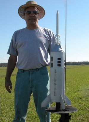
I wrote a bit about finishing this model in the construction section. I will therefore highlight some of my specific thoughts. First off was finishing the body tube. It had an extremely rough and porous surface as well as a deep spiral groove. I filled the groove first with Elmer's putty and then put a couple of coats of water diluted Elmer's Fill 'n' Finish on it. After this and a good sanding, I applied two coats of Topflite balsa finisher. I also only performed this process on the upper section of the tube that the wrap did not cover to minimize the work. Overall it produced a reasonably good surface although not perfect. The remainder of the rocket was made of the styrene sheet material that required no painting prep. The hardwood LES rocket was given a couple of coats of Rustoleum gray primer and sanding between coats produced a sealed surface for painting. I painted the overall rocket with Kyrlon flat aluminum paint and the LES rocket and tower with Krylon white. The tower was attached after painting since painting the cone and tower as one piece would have been basically impossible.
The decals were next. Sheri provided the United States lettering for the side of the rocket as decals. These were fairly simple to apply although when drying one off, it came free of the rocket and was destroyed. Sheri kindly sent a replacement. I used decal solution to get the decals to conform better to the corrugations on body wrap. The block patterns on the forward end of the rocket came as very thin stick-ons. I did not really want to use these as I was concerned as they aged they would start to peel. I therefore used the stick-on blocks to layout the pattern on the rocket and then masked and painted the block patterns using Krylon black paint. Overall the paint scheme was duplicated and I was very pleased with the results.
Construction Rating: 4 out of 5
Flight:
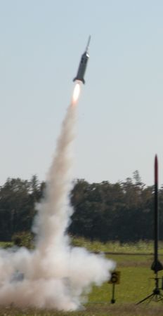
The engine mount is a 29mm diameter so it limits the selection of engines and being a rather heavy rocket a minimum of a medium power G should be used. Sheri recommends the single use Aerotech G40-4 engine for flying the LJ2. I could have bought one of these but had in stock an Aerotech RMS G64-4W. Also the G64 costs less to fly and has 12 Ns greater impulse than the G40. I flew the LJ2 for the first time at the 2008 Bunnell Blast in Florida. Not having an engine locking system installed, I wrapped masking tape around the engine for a tight fit and then also threaded a screw into the wooden centering ring next to the engine tube with the lip of the screw over the notch in the reload casing. I didn't want to have a possible misfire, which in the past I frequently had using Copperhead igniters, so I used a small electric match to light the engine. I packed a 60" chute from my PML Black Brant as Sheri recommended and used a Nomex cloth parachute protector to protect the chute from the ejection charge. The rocket flew off a quarter inch rod about four feet long. The wind was blowing about 5 mph at liftoff and the rocket weather cocked slightly into the wind at about a 20 degree angle off vertical but flew to about 250 feet. It descended a bit more than I liked prior to the ejection charge going off, a bit typical of AeroTech engines, but the chute then popped and blossomed immediately. It floated gently to the ground with one fin joint fracturing at touch down. I will fly it again and probably use the same engine. The engine mount tube is long enough that I might consider a longer reloadable 29mm engine in the future as well.
Recovery:
As noted previously I used a 60-inch parachute from my PML Black Brant. I plan on buying a 60-inch chute to permanently assign to the LJ2 in the future. Sheri did not include a chute or shock line system so I also installed a 12 foot length of LOC tubular nylon cord for the shock cord system which I tied to the braided wire I had previously installed in the rocket. During the flight, the shock system worked perfectly and the chute blossomed almost immediately after deployment. The rocket is a bit on the heavy side weighing over 2.5 pounds for flight and the 60-inch chute worked perfectly.
Flight Rating: 4 out of 5
Summary:
While being a bit let down upon my initial look at this kit when I opened the box and saw the parts, I ended up quite happy with the finished rocket. It was a true builders rocket as you can tell from the article. About the only pre-made part was the corrugated wrap and that required a bit of work as well. I personally actually like rockets like this as I enjoy building probably more than flying. I did spend a good amount of time building this rocket but the finished bird was well worth it. I got a few nice compliments at the launch site and had a good first flight. I think the big thing now is I hope I never get a bad flight and crash it, not because of the cost involved in cash but because of the time involved in building.
Overall Rating: 4 out of 5
Other Reviews
- Sheri's Hot Rockets Little Joe II By Tim Doll (October 30, 2008)
Sheri's Hot Rockets Little Joe II is a mid power (29mm engine mount), 1/30 scale model of the popular NASA test vehicle that was used during the mid 1960s to test the Apollo Launch Escape System. Sheri keeps a consistent "Buy It Now" presence on eBay or you can order it direct off her website . As of this writing, the list price is $89, although she does have occasional sales where she'll ...
- Sheri's Hot Rockets Little Joe II By Andrew Connors (August 10, 2007)
This kit is From Sheri's Hot Rockets, part of CJS aviation. This Little Joe II kit is a 29mm MPR/HPR 1/30th scale kit of the famous LJ2 QTV. It's a single stage 29mm configuration although you could cluster or use a larger MMT if you used thicker centering rings. Single BT made from heavy gauge kraft tubing and all four fins, body wraps, modules and the tower are made from styrene plastic. ...
 |
 |
Roger Smith (October 4, 2011)
Note: Sheris Hot Rockets are now produced by Red Arrow Hobbies and there have been no reports of problems with purchasing the kits from Red Arrow.
|
|
K.J. (April 3, 2010)