Squirrel Works Metropolitan Police Call Box
Squirrel Works - Metropolitan Police Call Box {Kit}
Contributed by James Gartrell
| Construction Rating: | starstarstarstarstar |
| Flight Rating: | starstarstarstarstar |
| Overall Rating: | starstarstarstarstar |
| Diameter: | 4.13 inches |
| Length: | 11.88 inches |
| Manufacturer: | Squirrel Works  |
Brief:
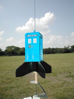
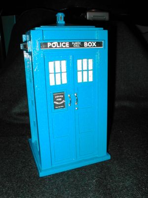
This newest kit from Squirrel Works is simply awesome! It is a very unusual but fantastic kit that sits atop a BT-55 booster. It doesn't grab a lot of altitude on the recommended 24mm D12-3 motor, but it does it in style. Very impressive! It makes an excellent low-flying park rocket with simply beautiful recovery on two big 24-inch red mylar parachutes. The face card in the kit is another true work of art, which is a signature of Squirrel Works kits. Parts quality is no less than excellent either. There are a quite a few self-adhesive decals to place on the rocket, but when you’re done, you could build a diorama around it and folks would swear they were looking at a real Metropolitan Police Call Box on the streets of London.
Construction:
The kit includes a ton of parts (I've listed the main ones):
- 1 BT-55 kraft booster tube
- 1 BT-55 kraft internal tube
- 14 laser cut balsa sheets (yep, that’s fourteen!)
- 4 pre-cut balsa structural components
- 1 standard 24mm motor mount kit with motor clip
- 2 BT-55 couplers
- 1 extra long 3/16” launch lug
- 1 screw eye
- 1 bag of BBs, for weighting
- 1 shock cord, 1/4” elastic
- 2 24” mylar parachute kits
- 2 decal sheets, self-adhesive
- 1 small parts bag of parts (door handles, centering rings, etc.)
Clear off your hobby table because you want to have plenty of room while building this kit. Also, you’re going to need some time to build this one. It isn't a one day build. Don has made it easy though with superbly illustrated step-by-step instructions. I lightly sanded all the exterior balsa for the Call Box with 400 grit sandpaper. I wanted the wood grain to show on this one, so I didn't use any balsa filler except on the booster fins, gussets and joints. The booster tube seams were hardly noticeable and only required minimal filling. Construction is really not that difficult, but you’re going to do a lot of things four times, once for each side. I can't imagine having to build the kit from scratch. I would probably give up after cutting out the parts for one side. Thank goodness for laser-cut parts!
I first sanded all of the tubes and centering rings with 240 grit sandpaper inside and out to improve adhesion of the parts glued onto or in them. Except for the balsa gussets glued into the fin/body tube joint, the motor mount and booster are your standard build. The fins are really big, since they have to extend beyond the edges of the call box for the aerodynamics, so those gussets really improve the strength of the fin/tube joints. I was sure glad Don added that improvement (see recovery). A fin-marking guide is provided to align the fins on the tube. I papered the fins to improve strength and finish and used Elmer's Fill 'n' Finish to fill in the tube/fin/gusset joints. Build the motor mount and install it into the rear of the booster tube with a coupler installed in the front of the booster to connect with the upper internal tube. Two motor clips hold the booster and upper internal tube together one on either side to allow the booster to be separated for displaying the Call Box. Measurements for installation of the two motor clips are crucial as you want them to hold the booster as tightly as possible. I used 5-minute epoxy to glue the upper portion of the clips onto the internal tube and wicked in some CA into the tube before cutting the slits where the clips insert. These areas will receive a lot of stress from motor ejection and removal for display so I wanted them to be really strong. Next, the launch lug is glued onto the side of the internal tube, then slide the bulkheads on and glue them onto the tube at the indicated positions. Construction of the side panels comes next.
Various laser-cut pieces are glued onto a solid panel. Glue this part here, glue this part there, glue these pieces together and then glue it there, etc. until you have a completed side panel. Then do that three more times! This is where that cleared off hobby table becomes necessary. It will look like you have a lumberyard on your table to start and then, slowly, four beautiful side panels remain. Awesome! Next, install the panels and support beams onto the internal bulkheads. Align a panel on one side and glue that, then glue on a support beam and continue around the internal tube until all of the panels and support beams are installed onto the bulkheads. If you get the first panel aligned properly at the beginning, there is just enough room to install the final support beam without any trim sanding. I test fit all of the panels and support beams first and then marked one of the panels to start. This is a little difficult since you have eight parts to deal with, but it's worth the effort. Also, before gluing on the fourth panel and support beam, I put glue fillets on the internal panel/beam and panel/bulkhead joints of the other three panels. You can't access this area once the fourth panel is installed. Then, I put extra glue on the internal side of the bulkhead and beam so that after gluing on the fourth panel and beam I could lay it on its side and allow the glue to drain down to make a fillet on the fourth panel/beam panel/bulkhead joints. While that assembly is drying, you can move on to construction of the base and top.
Similar to the panel construction, the base and top panels are constructed by gluing various laser-cut pieces onto a solid piece. Be careful to assure that the pieces with the holes for the launch lug are aligned before you glue things together though. Once finished, these are glued onto the internal tube/panel structure. Be sure to put your glue fillets on the rest of the internal structure joints before the top and bottom panels are installed. Also, here again, be sure to align the holes with the launch lug before gluing on the top and bottom panels. The top panel has a recess that will hold the BB weights. After the glue has set, pour epoxy into the recessed area of the top panel and then pour the BBs into that and level them out. Actually, I waited until after the rocket was finished to add the epoxy and BBs. That way, it was easier to handle while finishing. OK, things are really starting to look great! The “nose cone” is built next.
The nose cone has a structure with four triangular pieces that when pushed together create the domed top. This is really the only tricky step since the glue on the first three pieces needs to be almost set before gluing the last side of the fourth piece. It is an impressive piece of engineering though. A stick of balsa is glued into the center of the top that extends through the bottom. The light unit is glued on top of that and a coupler is glued around it on the underneath side with a laser-cut piece of balsa glued into the center of the coupler and to the base of the balsa stick. The screw eye is then glued into that. I wicked CA into the coupler and balsa center for strength and durability since they will be exposed to the ejection gases. Construction of the light unit that is glued onto the top was a little difficult too, because the pieces are so small and my hands shake a lot when trying to build something that small. Tweezers and patience are a must! That leaves the installation of the shock cord and assembly of the parachutes.
I added a 6-inch length of Kevlar to install in the shock cord mount, which is part of my standard installation. I put CA around the forward end of the tube and tied a knot in the Kevlar at the exit point to protect against abrasion then added a loop at the end of the Kevlar to tie on the 1/8” elastic cord. Lastly, the shock cord mount and shock cord was installed and connected to the screw eye in the nose cone. Put the parachutes together and you’re done.
Finishing:
Since I wanted to leave the wood grain in the finish of the Call Box, I was very careful as parts were glued together to keep everything neat. That way, I wouldn't have to do a lot of clean-up sanding and heavy primer before finishing. The booster was painted all black as suggested in the kit. I decided to go with the London blue finish rather than the Scotland red on the Call Box. The plastic tube in the light unit was masked off using liquid mask and then the entire unit was painted, scraping the liquid mask off with a hobby knife after the paint had set. Don suggested installing the plastic tube and top of the light unit after painting, however, I don't think I would have been able to get those four little posts installed properly without having the plastic tube installed for support. I did hold off installing the door handles until after painting. I inserted them into the balsa using the nails and then removed them and placed a drop of CA in the holes and re-installed them. A variety of the self-stick decals are provided for various Call Box versions. This is another one of those tedious steps. Each windowpane decal has to be removed from the decal sheet and laid into the windowpane--all 48 of them! If anyone can think of a better way to do that, I'd sure like to hear about it. The remaining decals were installed, and voilà, a completed Call Box. Next, I applied a couple of coats of Future floor wax to the painted surfaces to protect the finish and improve the shine. Calling all cars, calling all cars, she's ready to launch! Woohoo!
Construction Rating: 5 out of 5
Flight:
Fitting those two big chutes into the tube with the wadding and shock cord is a bit difficult and takes some practice. Also, make sure you have at least three feet of rod length to travel if there is any wind. I had probably less than 2.5 feet of rod in a 5+ mph wind using a three foot rod on an AeroTech Mantis pad with a spent engine casing holding up the rocket off the blast plate. The rocket arced off the pad at about 20 degrees into the wind, which reduced an already low altitude fairly significantly. I was also using an older D12-3 that might not have had the full thrust of a new one. If it ever stops raining here so I can fly again, I’ll update the flight stats as I would anticipate a much more vertical flight using a newer motor and more rod length.
Recovery:
The chute popped right past the top, but that was probably only 100 feet or so from the ground. Thank goodness for a 3-second delay that really was only three seconds. Those two big 24-inch chutes look impressive as they deploy. Unfortunately, it landed on the asphalt parking lot. That's a pretty good test of the importance of those fin gussets. It passed! It landed almost vertically and everything survived with only minimal initial surface damage where the fins hit the ground. The concussion upon landing pushed up the first fin to hit the ground into the lower portion of the Call Box and cracking a small piece on the base. I put a little CA on that and held it together and you can barely tell it's there. After landing, it fell onto its front panel and just before I got to it, a gust of wind dragged it three or four feet across the parking lot. Ouch! Did you know that asphalt is very abrasive? That was the worst damage it suffered. It still looks great though as the abrasions are hardly noticeable until you look really close up!
Flight Rating: 5 out of 5
Summary:
Wow! I can't describe the degree of satisfaction I felt after finishing the Call Box. Don has included a lot of “engineering” in the kit that is spectacular and makes building the kit a lot easier than I was expecting. While the kit can probably be built and finished in a couple of days, I would plan on savoring the build over about a week's time. Take your time and you will produce a beautiful work of art that is sturdy enough to fly over and over again. There are few kits that will out impress your Call Box on the launch pad. Glorious!
PROs: Everything! The Call Box is a complex design that has been “engineered” to make the build relatively easy. The provided decal choices allow the builder to choose a variety of looks that will separate their kit from others. Parts quality is superb. The laser cutting is excellent. The instructions are excellent, and you get a nice long shock cord and two big parachutes for a gentle recovery.
CONs: I made the change with the shock cord, but that is just personal preference.
Overall Rating: 5 out of 5
 |
 |
Flights
|
|
|
|
J.L.M. (September 12, 2007)