The MIRV's first/booster stage
Contributed by Rich DeAngelis
This whole assembly is fairly light and returns with tumble recovery. I intend to paint some silver stripes over the black so it can be seen in the grass. It is only expected to go a few hundred feet with a C6-3 lifting all the weight of the second stages. Wondering if I should paint the wood launch lug silver too, or just sand it back to natural. I think paint should protect it better.
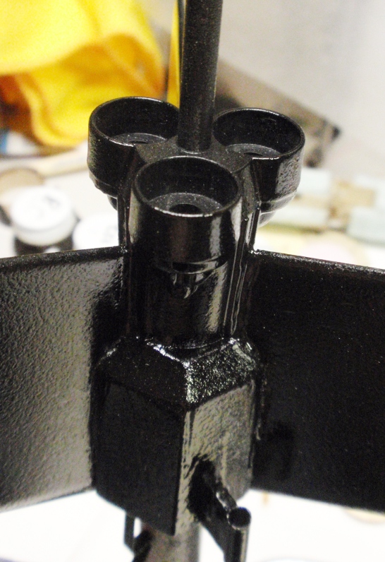
This closeup of the MIRV's booster stage shows the major components. From the top downwards, first is the dowel used as a launch rod for the second stages. The dowel sits in a molded plastic manifold which directs the ignition gasses to all three 13mm second-stage motors which sit in the three holes. Under the manifold it connects to the 18mm engine tube. Surrounding the engine tube (not visible here) is the styrofoam block where the lower launch lug is attached. This foam block also serves to align the three balsa fins which are glued to the engine tube and foam. The six facets of the styrofoam block that face towards the upper engines have little silver stickers (not applied yet), I think Estes supplied them to act as a shield from the second-stage engine blasts.
Estes didn't mention it in the instructions, but I stuffed old 13mm motor casings into the manifold tops before spray painting. I didn't need paint to gum up the insides. I can only imagine how bad it could get after the paint starts charring and blistering.
Related Builds
 |
 |