| Construction Rating: | starstarstarstarstar |
| Flight Rating: | starstarstarstarstar |
| Overall Rating: | starstarstarstarstar |
Brief:
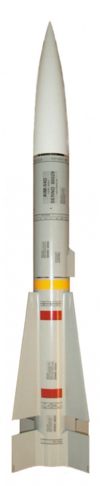
The THOY Phoenix is a near half scale version of the original Phoenix/AIM-54 used by the U.S Navy as a long range air to air missile. This 4” diameter High Power rocket stands 46” tall and is currently produced by Rocket R & D, who bought the rights to all THOY kits.
Construction:
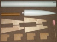
My kit was ordered directly from Rocket R & D, as all the dealers I called were out of stock. They cut me a new kit that day and I had it within 3 days of the order, which is excellent service in my book. It came bagged with a 4” plastic ogive nose cone, 4” diameter heavy paper body tube pre-marked with fin slot and launch lug locations, a phenolic 38mm motor mount, ply centering rings, pre-cut 1/8” plywood fins, 29mm motor adapter, shock cord and cable, ½” launch lugs, a 30” bright orange circular parachute, a VERY impressive detailed decal sheet and a two page instruction manual. All parts are of very good quality, although I was a bit surprised that the shock cord was 1” elastic, which appears to be older technology.
 The only problem I had with the kit was with the long upper stabilizer fins, as they had warped a bit by the time I received them. I eliminated this problem by soaking the inside curved side with water and a sponge, then supported the ends and weighed down the center so the fins were bowed the other direction. An hour or so later, the water was dried and the fins were straight again.
Fifteen-minute epoxy was used throughout the construction, which begins with the assembly of the motor mount. Thoy uses a steel cable with crimp ends, which is looped through two holes in the top centering ring and crimped, prior to assembling the motor mount. As extra insurance, I soldered the wires at the crimp joints for additional strength. The shock cord was then tied and tack glued to the other looped end. I will see how the shock cord holds up after a few launches, then I may replace it with tubular nylon.
Next, the instructions have you epoxy the centering rings to the motor tube, then glue the assembly inside the body tube. I would recommend that you epoxy only the top centering ring; use the bottom centering ring only for alignment until the top ring's epoxy has set inside the body tube. This will allow you to remove the lower centering ring so you can get some good glue fillets at the fin base where they attach to the motor tube. I followed the instructions to the letter and wound up using Aeropoxy for fillets, which had to be applied through the fin slots. This was a bit difficult to do, however, if you make the bottom centering ring removable, you can easily add fillets and glue the lower centering ring flush to the bottom of the body tube after the fins are completed.
Included in the kit was a 29mm adapter, which was simple to construct and was next in the build process.
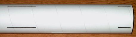 After this was completed, the fin slots were cut out using an exacto knife. You will have to measure the length of the slot yourself, as the markers are only vertical. I used an upper fin as a template for slot length. Just be sure to measure from the bottom of the tube to the bottom of each slot and keep this distance equal for each upper fin set.
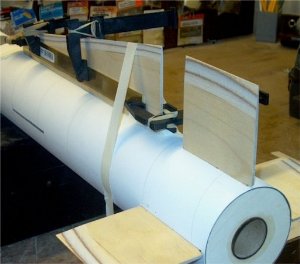 Next, you taper the edges of each fin; a table sander cut this work down considerably and they turned out pretty nice. Just make sure not to take of too much wood on the taper. Once this was complete, the lower fins were glued to the motor mount and body tube. Note that the “through the wall” fins appear to attach fine, even though the TTW mounting does not extend the full length of the fins. Some fitting is required prior to gluing the fins, so make sure you “FIT” each fin before gluing. I numbered each fin and slot to make sure they would be installed in the slot to which they were fitted. Also, I had to sand some length off the inside tabs as they were a bit too long on the two tabs for the surface area to sit flush with the body tube. Masking tape was used to hold each fin in place until the epoxy cured. Once the lower fins are epoxied, glue on the upper fins, insuring they align properly with their lower counterpart. If you opted to keep the lower centering ring removable, now is the time to add fillets at the motor mount joints, then glue the lower centering ring flush to the bottom of the body tube.
I decided to glass the fins and body tube for additional strength, rather than seal them with sanding sealer as the instructions recommended. Finishing resin was used to fiberglass the fin area since it has a long cure time and really soaks into the wood. The upper portion of the body tube was glassed separately using 30 minute epoxy, which left a nice, easy to sand finish and added some weight up front where I wanted it. Before glassing the upper tube section, the cloth was “tacked” on lengthwise using Cya so it could be pulled tight around the tube without shifting. Once all glassing was completed, the excess cloth on the fin edges was removed, and then edges were sanded and shaped. Finally, the entire rocket was sanded using 120 grit paper to start and I finished with 320 grit sandpaper. It turned out very well and glassing did not seem to add much weight to the model, even though I know the weight will show up when finished.
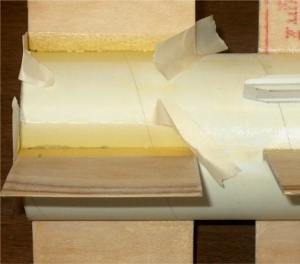 Fillets were added next; smaller fillets were applied to the long stab fins by hand, while the lower fin fillets were made using masking tape as a “dam” to hold the epoxy. Thirty-minute epoxy was used for the lower fillets; heating it in the microwave prior to mixing made it nice and thin along with “bubble free”. It also cut the set time down to about 8 minutes.
Once all fillets were added, the launch lugs were attached. You get a single piece ½” heavy paper tube lug, which is cut at an angle into two pieces. I used a 30” piece of ½” steel rod to hold the lugs in place until the glue set. One nice feature was the fact that the body tube was pre-marked for lug placement, which takes the guesswork out of where they need to be mounted. Filets were add to the lugs using the same method as described for the lower fins, however, I made sure the entire lug, including the top, was coated with epoxy for strength. Once the lug fillets were shaped, I glazed the bottom centering ring with epoxy for a smooth waterproof finish.
The nose cone came with a good-sized clump of clay for added nose weight, which was epoxied into the nose cone tip. After the first flight, I will see if any additional weight may be needed and epoxy some lead shot in the nose cone if necessary.
Finishing:
Final sanding was done in the fillet area using 100 grit paper, then finished with 150 grit sandpaper. White Krylon primer was applied next and I used 150 grit to cut away any excess epoxy resin left from the fiberglassing and to blend in the cloth seams. Use an electric sander in the glassed area, which will cut through the epoxy nicely and blend glass seams well. A few more coats of primer were added, then I wet sanded with 320 grit. Two more coats of primer were added and I finished it up by wetsanding with 400 grit. Any small filling was done next, then two final coats of primer were added and wetsanded with 600 grit wet/dry sandpaper. Light Gray Glossy Krylon paint was used on the body tubes and fins, which left a nice and smooth surface to apply decals. The nose cone was done in Krylon Flat White. I used Testors Gloss Red and Yellow for the 1” stripes and used a piece of Monokote self stick Chrome for the silver section. Once all decals were applied, TopFlite Clear Dullcoat was applied for the flat military look. When applying the Dullcoat, you must use light “dusting” layers; the Testors stripes you painted will orange peel if you put it on too thick. Note that the stripes and decals were not added until after the rocket’s first flight. Finally, the nosecone and parachute were attached per the instructions. Don't forget to tack glue your knots with a drop of epoxy. I did purchase and install a 1” steel link so the parachute could easily be removed later for storage. Next, three holes were drilled in the bottom of the tube for a PML motor retainer and the retaining slugs were installed. As a last step, I drilled two 1/8” holes in the side of the upper body tube, just a few inches below the nosecone seat to prevent pressure ejection.
Construction Rating: 5 out of 5
 Flight:
My rocket weighed in heavy; 3lbs 11oz when comparing to the WRasp charts of 2.2 lbs. I can account for the extra weight though, since I always try to build strong and wound up adding some weight with glassing and big fillets.
This is a basic, motor ejection deploy model, which makes prepping it pretty straightforward. One other item that was added was a large Nomex® parachute protector, so I wouldn't have to deal with wadding. The rocket was prepared and I did have to add some masking tape to the base of the nose cone for a good fit.
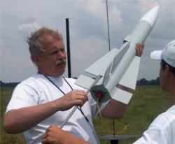
 My first launch was on a H242T with a medium delay. I opted for this load because a H123 would not have been enough for a model of this weight and it was a bit windy outside, which told me to use something to get it off the pad quickly. The Phoenix was placed on the pad and we awaited the countdown. The H242 Blue Thunder ignited immediately and lifted the Phoenix with authority! It was a very stable launch and no windcocking occurred, even with those large fins. What was really cool was the “whistling” sound it made while slowing down as it reached apogee; kind of sounded like an incoming missile; Really cool!!!
Recovery:
The parachute deployed about a second after apogee, so the medium delay was a bit too much, but a short delay would be way too short; some tuning will be required to get it just right. The Phoenix landed safely, but downwind a bit, so I had to walk a good distance for retrieval. The rocket was in perfect condition and I was very pleased with the first flight of this bird. The Nomex® protector worked great and the parachute was in like new condition with no scorch marks. There was some powder buildup on the lower section of the shock cord where it attaches to the steel cable, but it still looks good. I do like the current location of CG, which is right at the leading edge of the long fins. I want to keep the same stability, but use a large motor for the next launch, such as a I 161, so I’ll check the weight difference in motors and add some lead shot to the nose cone for compensation of motor weight. Altitude appeared to be around 1200-1400 feet for the flight, however, high winds kept me from launching again that day.
Flight Rating: 5 out of 5
Summary:
Summary: The THOY Phoenix is a “test proven” model that has been around a long time and still remains a great flier! I am very pleased with this model and recommend it to everyone; its looks and performance seem to appeal to a large group of fliers, which is why it has stood the test of time. Construction was very simple and the problem I had with the warped stab fins was to be expected; the warping was minor so I do not consider this an issue. I am, however, still very leery of the elastic shock cord and feel it's a matter of time before it gives, so I will probably replace the cord with tubular nylon of appropriate length. Also, the very detailed decals really bring out the looks of this bird. In summary, if it's military you like and performance you want, the Phoenix is a must have model for your silo!!!
Overall Rating: 5 out of 5
Other Reviews
- THOY Phoenix By Ted Phipps
Constructing the THOY Phoenix This is a high power rocket kit originally developed by Tiffany Hobbies Of Ypsilanti (Michigan?), and now produced by Rocket R&D. The suggested motors run from G to H, but unless you build very light, G’s might work only on absolu tely calm days. I won this kit in an online raffle sponsored by Magnum Hobbies almost three years ago, but waited ...
 |
 |
Flights
|
|