| Construction Rating: | starstarstarstarstar_border |
| Flight Rating: | starstarstarstarstar_border |
| Overall Rating: | starstarstarstarstar_border |
| Diameter: | 1.00 inches |
| Length: | 20.00 inches |
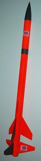
| Manufacturer: | U.S. Rockets  |
| Skill Level: | 2 |
| Style: | Multi-Stage |
Overview
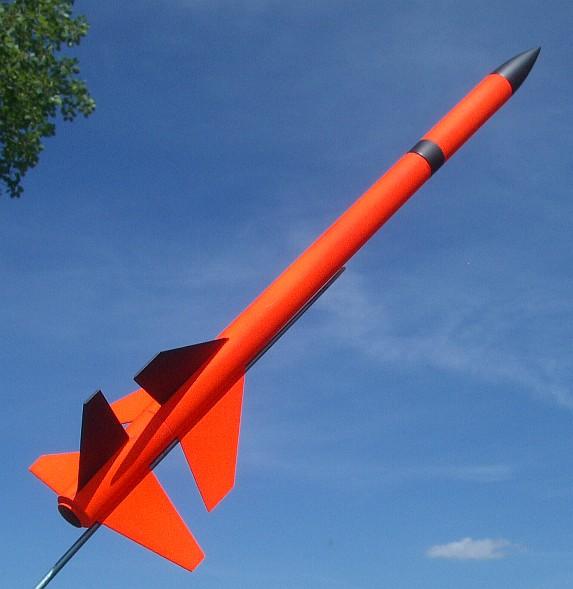
A direct-staged 2-stage rocket that flies on 18mm engines and includes a small payload bay.

Kit Specifications (from Cover Art)
- Length: 20" (508mm) Sustainer, 23" (584mm) Total
- Diameter - 1.0 inches (25mm)
- Weight - 0.92 lb (1.47 oz) (42g) *
- Skill Level 2
Background:
Nick at EMRR sent me this kit when I became a Featured Reviewer for EMRR. This
was my first experience doing a staged rocket, as well as my first experience
building a US Rockets kit.
The kit is packed in a standard clear plastic bag with a paper hang tag.

Parts List
- 1 BT-9-12 Airframe Tube
- 1 BT-9-5 Payload Tube
- 1 BT-9-3 Stage Tube
- 2 TC-9-3 Couplers
- 1 PP-9 Payload Plate
- 1 SE-0 Screw Eye
- 2 BT-7-2.75 Motor Tubes
- 4 CR-9-7-1/4 Centering Rings
- 3 Miniroc Fins
- 3 Fire Forget Fins
- 1 SCM- Shock Cord Mount
- 1 SC-5-1/8 Shock Cord
- 1 SM-3 Streamer
- 1 NC-9 Nose Cone
- 1 LL-1/8-2 Launch Lug
- Instructions
- AR 2B Decal Sheet
- AIR-3 Tech Report
The tubes are thicker than Estes BT-50, and have a smooth white glassine finish
with minimal spiral. The pre-cut plywood fins had some fuzzy edges that clean
up easily with a little sandpaper. The tube couplers are not standard brown
kraft paper; they have the same white glassine coating as the body tubes. The
shock cord is a very generous 55 inches long.
My kit was missing the Shock Cord Mount (easily re-created from a piece of
paper), and I got an extra launch lug.
The instructions are printed on four 8.5x11-inch pages on orange paper. The directions have lots of text and a goodly number of computer-generated illustrations.
CONSTRUCTION
Construction is relatively straight-forward, and this would probably be a
Skill Level 1 kit if not for the staging.
The first step is to taper the edges of the precut plywood fins with
sandpaper. Next, the body tubes are marked using a marking guide (not the
wrap-around kind, though), and the lines are extended using a door jamb. Then
the fins are glued to the body using wood glue. I used the G. Harry Stine
double-glue method with Titebond-II wood glue. To ensure that the upper fins
lined up with the lower ones, I temporarily connected the two stages using the
stage coupler and a used engine, then used a straightedge clamped to one fin to
align the other fin.
After the fin joints have dried, the launch lug is cut in half and glued
against the base of the fins.
Motor mounts are built for each stage using BT-20-size tubes along with two
centering rings each. The spacing of the rings is somewhat non-standard and
must be done correctly to allow the stages to mate properly later. The
directions explain this clearly.
1. Increase the overhang on the booster mount from 1/8" to 1/4" to provide a larger surface for taping the engine to the tube.
2. Trim 3/8" from the front of the booster mount tube to allow room for the cellophane tape used to join the upper- and lower-stage motors to each other.
3. Insert a thrust ring into the front of the sustainer motor mount.
None of these modifications are required, but I think they making the flights a little more reliable and easier to prep.
The motor mounts are glued into the body tubes and a stage coupler is glued
into the lower body tube with 1 inch protruding out the top.
A standard tri-fold paper shock cord mount is used to anchor the shock cord
to the bottom half of the sustainer. It is important that it be inserted at
least 1.5" deep into the tube, since the upper stage shoulder is at least
that long. I recommend inserting it even deeper than that to make it easier for
the streamer to deploy cleanly.

The payload section is constructed from a 5-inch piece of body tube, a
plywood bulkhead, screw eye, and a tube coupler. A pink plastic streamer (looks
like construction site ribbon, 3" x 45" x 0.004") is taped to
the shock cord between the sections. (I glued and stapled mine to ensure that
it stayed attached.)
")
Finishing:
Finishing is pretty standard: Sand, seal, sand, seal, sand, prime, sand,
paint. I skipped the sealer and used a single thick coat of Kilz primer to fill
the grain and spirals, sanded most of it off, then a light coat of Rustoleum
Painters Choice white primer.
The directions recommend painting the booster flat black and the sustainer
fluorescent colors. I used a Rustoleum Fluorescent Red-Orange on most of the
model, and Rustoleum Painters Choice Flat Black on the nose, one fin of each
stage, and a band on the payload bay.
My final weight with paint and glue was 2.44 oz for the upper stage and 3.15 oz total, which was exactly the weight of all the parts that I started with. The little bit of booster motor tube that I trimmed off must have weighed the same as the paint that I added.
Construction Rating: 4 ½ out of 5
FLIGHT/RECOVERY
Recommended Motors
| Booster |
Sustainer |
|---|---|
| A8-0* B4-0* B6-0 C6-0 |
A8-5 B4-6 B6-6 C6-7 |
| Engine Combinations |
Max Alt
(feet) |
| B6-0/A6-4 | 542 |
| B6-0/A8-5 | 572 |
| B6-0/B4-6 | 859 |
| B6-0/B6-6 | 867 |
| C6-0/B6-6 |
1297 |
| B6-0/C6-7 | 1458 |
| C6-0/C6-7 | 1809 |
Flight Preparation
Here are the steps for flight preparation:
- Apply masking tape as needed to assure proper fit of nose cone, stage coupler, and payload bay.
- Insert recovery wadding.
- Fold and pack the shock cord and streamer.
- Insert payload bay.
- Temporarily insert the upper-stage motor and check the balance point. It should be at least 1 inch forward of the leading edge of the sustainer fins. If the CG is behind that, add weight to the payload bay to move the CG forward.
- Tape the two engines together using a single wrap of cellophane (Scotch)
tape. [This step is not called out in the
directions, but I think it is prudent.]
- Insert the engines into the upper stage.
- Wrap a layer of masking tape around the upper engine and the upper engine
mount tube. Do not let this tape overlap the lower engine.

- Slide the booster stage over the lower engine.
- Wrap a layer of masking tape around the lower engine and lower engine mount
tube. Trim excess tape.
- Check the balance point again with both stages loaded. It should be at
least 1.4 inches forward of the booster/sustainer seam. If the CG is behind
that, add weight to the payload bay to move the CG forward.
- Insert igniter and plug.

Test Flights
 The maiden flight was on a warm day in early July. Winds were
blowing up to 10 MPH so I decided to stay with a small motor combination, B6-0
/ A8-3 and angled the pad about 20 degrees into the wind. Takeoff was not real
fast but not real slow either, and the rocket angled even farther into the wind
before it picked up much speed. There was a slight hesitation when the booster
thrust ceased and the sustainer kicked in. The sustainer then zoomed away
downrange at a brisk pace. Just after apogee, the nose ejected and the streamer
deployed. Landing speed was fairly fast, but both stages landed on grass so
there was no damage. Perfect flight! What a nice introduction to staging.
The maiden flight was on a warm day in early July. Winds were
blowing up to 10 MPH so I decided to stay with a small motor combination, B6-0
/ A8-3 and angled the pad about 20 degrees into the wind. Takeoff was not real
fast but not real slow either, and the rocket angled even farther into the wind
before it picked up much speed. There was a slight hesitation when the booster
thrust ceased and the sustainer kicked in. The sustainer then zoomed away
downrange at a brisk pace. Just after apogee, the nose ejected and the streamer
deployed. Landing speed was fairly fast, but both stages landed on grass so
there was no damage. Perfect flight! What a nice introduction to staging.

The next two flights occurred on a breezy day late in July, with winds from 5 to 10 MPH. Flight #2 used a B6-0/B6-6 combination. After a straight takeoff, it angled into the wind a little bit. There was a brief wiggle when the second stage lit, then the upper stage angled into the wind a bit more. Ejection was a bit after apogee. The large streamer deployed well and carried it downwind across two soccer fields and nearly into a men's soccer game in progress.
To prevent the wrath of a few dozen sweaty soccer players, I decided to
angle flight #3 into the wind about 5 degrees when I moved up to a C6-0/B6-6
combo. The longer burn of the C6-0 was much more satisfying than a B6-0, and
the B6-6 lit perfectly. It did quite a bit of weathercocking and headed out of
the soccer field and over some apartments on the upwind side of the field.
Fortunately, the wind carried it back over the apartments to the grass at the
edge of the field.
On both flights the booster landed on the same fin and on both flights the
fin-body joint got cracked, even though the grass was quite soft. For flying
over hard surfaces, it might be a good idea to replace the streamer with a
parachute.
Flight Rating:4 ½ out of 5
OVERALL:
A good solid performer that should be able to handle a lot more impulse than I
dared to feed it.
PROS:
- Sturdy components.
- Clean styling.
CONS:
- Prepping requires heavy use of masking tape.
Overall Rating: 4 ½ out of 5
 |
 |
Flights
|
|