| Construction Rating: | starstarstarstar_borderstar_border |
| Flight Rating: | starstarstarstarstar |
| Overall Rating: | starstarstarstarstar_border |
| Manufacturer: | West Coast Rocketry |
Brief:
This is a 4FNC rocket designed to fly on 29mm E-H power and has parachute recovery and payload bay.
On eBay, I found a group of rockets from the defunct West Coast Rocketry. I put a bid in on all of them and "won" only the mid power ones. This is the first one I have gotten around to trying to build.
Construction:
There is much about this kit that is minimalist. That includes the packaging. All of the components were in a clear
plastic bag stapled at one end. They appeared to be in good shape and consisted of:
- Motor tube
- 2 centering rings
- plywood bulhead
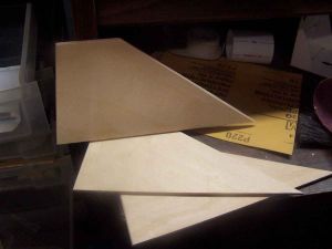
- 4 plywood fins
- 1/4" launch lug
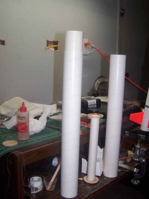
- 2 18" body tubes
- a payload bay
- a turned balsa nosecone
- 2 couplers
- an eye screw
- a parachute kit
- an instruction sheet that brings new meaning to "minimalist"
The first step in the instructions was to epoxy the centering rings 1/8" from either end of the motor tube. The rings fit perfectly and needed no sanding. The gluing was done with 5 minute epoxy. When it had set up, I epoxied the other side and put in a good fillet.
 The next specified step was to mark
the body tube for fins and then install the motor tube in the aft end. I wanted the epoxy to have a better chance to
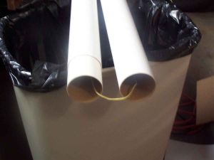
harden so I skipped to the next step which was to join the two body tubes with a coupler. Again, epoxy was specified. I
swabbed in the epoxy to one end of a BT and then inserted a coupler to the halfway point.
The next specified step was to mark
the body tube for fins and then install the motor tube in the aft end. I wanted the epoxy to have a better chance to
harden so I skipped to the next step which was to join the two body tubes with a coupler. Again, epoxy was specified. I
swabbed in the epoxy to one end of a BT and then inserted a coupler to the halfway point.
The centering rings that fit so well around the motor mount needed some work to fit into the body tube. Sanding the perimeter eventually got a smooth fit. Before installing the motor mount, though, I decided to fashion a Kevlar® recovery system around the mount.
Presumably, this was not the intent of West Coast Rocketry, although I really have no idea what kind of recovery system they envisioned. The kit comes with a fairly generous piece of 1/4" sewing elastic but the instructions are silent on the issue. The only mention is several steps down where it says, "install your recovery system". As I said, the directions are minimal.
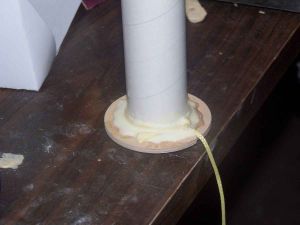
I tied a piece of Kevlar® long enough to run through both BTs around the motor mount near the forward end. I then cut a notch on the outside of the ring in order to pass the Kevlar® through. Before installing the mount though, I pushed the Kevlar® down around the ring, got the standing end lined up with the notch and filleted it in place around the ring with yellow glue.
While the glue was setting up, I took a closer look at the fins. They were of good quality plywood and I decided to round off their leading, trailing and outside edges. I did this by the expedient method of setting each fin in a vise and then using a strip of 150 grit sandpaper to take the edges off, working them back and forth like a shoe shine rag. I found that I got better results if I did not pull down but on one side at a time. I held the other end perpendicular to the plane of the fins. After doing a dozen or so strokes, I would make the other side "down". This did not result in a perfect job but it was good enough for me.
The fins took a while so the glue on the Kevlar® was dry enough to work with when I got back to the motor mount. I placed the Kevlar® in the notch and tied a ballpoint pen to the far end of it. I then used the weight of the pen to pass the Kevlar® through the first BT. When that was done, I mixed up another batch of 5 minute epoxy and used a long swab to place a ring around the interior of the BT about 6" in. I placed my foot on the far end of the Kevlar® and made sure the other end was in the notch of the first centering ring. Then using my foot to keep the Kevlar® under tension I slid the mount in about half way. Another ring of epoxy was then placed right inside the aft end of the BT and always maintained tension. I slid the motor tube the rest of the way in until the aft end of the motor tube was flush with the aft end of the BT. I then turned the assembly upright to cure. After about 10 minutes, I turned it over and applied an epoxy fillet to the joint between the BT and the centering rings.
Next up was the joining of the two body tubes. I fed the Kevlar® down the upper tube and then laid the two side by side. I mixed up some 5 minute epoxy and swabbed the interior of the upper tube and the aft end. Then, keeping tension on the Kevlar®, I slid the two pieces together and ensured they were straight.
The instructions give no marking guide of any type for the fins and say only to locate them 120 degrees apart. Since this rocket is too heavy for my Art Rose jig and did not seem to correspond to any of the BTs on my Estes alighment jig, I decided to make my own wraparound using VCT. This is the first time I have actually used that software.
The input needed for the software was the BT diameter, the length of the fins, the number of fins, the spacing (equidistant) of the fins and the thickness of the fins. The result was a wraparound template that fit perfectly and which gave not only the centerlines of the fins but the outside edges as well. Since this kit required the cutting of slots for the fins, it was very helpful.
The instructions did not indicate how far forward the fins were supposed to be located. Since there was no picture of the completed rocket, I just had to guess. I assumed they were not to be flush with the aft end since the slots had to be cut and that would interfere with the aft centering ring. For some reason, I did not even think of interference with the forward centering ring. To my eye, the extra paper on the aft end of the fin guide looked just about right so I decided to go with that distance. As I was to learn, that meant I just barely cleared the forward centering ring.
This was the first time I had ever had to cut fin slots in a rocket. The instruction provided no guidelines so I made up the procedure as I went along. I had the guide taped where I wanted it and then started to lightly draw a razor knife over the fin edge marks on the guide. With each pass I cut a bit deeper into the BT and finally, I had the slot cut out. It wasn't pretty but it would have to do. I evened up the edges just a bit by running a sanding stick through the slots. This removed the major bumps. The process was repeated for the remaining 2 fins.
In order to let my nerves recover some what from the process of cutting the slots, I did not immediately mount the fins. Instead, I got to work on the payload bay.
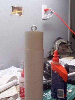
A pre-drilled plywood bulkhead is supplied which is supposed to be mounted in the remaining tube coupler. Unlike the centering rings, this was not a good fit. It slipped into the coupler and when centered did not quite touch the tube anywhere. Groaning, I screwed the eye screw into the bulkhead and then made up another batch of 5 minute epoxy. I liberally coated the entrance to one end of the tube and used the eye screw to push the bulkhead in. I then held it in place until the epoxy had set up enough to hold it. It was still a tenuous connection. I mixed another cup of epoxy and poured the whole thing into the aft end of the tube. I used a stick to smooth it out and when cured, now have no worries about the bulkhead holding. A bit more epoxy saw the coupler into the payload bay.
Getting back to the fins, I was in a quandary. I did not believe the fins were to be affixed to the motor mount; their shape was wrong for that. The fact was, I did not no how deep to set the fins. I finally decided that the slot was to provide a shearing surface and that the fins were just to be inserted the thickness of the BT. I made up another batch of epoxy and slathered it into the slot and then set the fin in place. I had to work it a little to get it to an even depth which was probably a good thing. That meant that the epoxy was starting to stiffen when I was ready to let go. I used my eyes to get the alignment right and then let it set for a while before progressing to the next fin.
To fillet the fins, I used 12 minute epoxy. I tried using masking tape to form "dams" and poured the epoxy into the grooves and used a popsicle stick to smooth it out. Just as it would start to set up stiff, I peeled the tape away. The results are not as perfect as I would like but they are definitely better than my first method.
PROs: Easy design
CONs: Inadequate instructions
Finishing:
After completing the assembly, this rocket sat around for a few days as I dealt with "real life". It came
to the forefront again when I learned that I had a rare launch window for bigger stuff in a week's time and I rushed
over to my build facility thinking I wanted to have this one ready.
 I set the rocket up in my booth
without bothering to look at it closely and started spraying with Kilz. Then I took a closer look at the nosecone and
realized that I had not sealed it or the fins. I figured the fins are plywood and the Kilz will seal that alright. I'll
have to see what happens with the NC.
I set the rocket up in my booth
without bothering to look at it closely and started spraying with Kilz. Then I took a closer look at the nosecone and
realized that I had not sealed it or the fins. I figured the fins are plywood and the Kilz will seal that alright. I'll
have to see what happens with the NC.
As it happens, the Kilz did an adequate job of filling the grain on the balsa nose cone. After sanding, I gave it a second coat of Kilz and let that dry. I sanded again and found that the finish, while not perfect is good enough especially in light of some of the other cosmetic defects present on this rocket as a result on my sloppily applied epoxy.
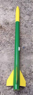
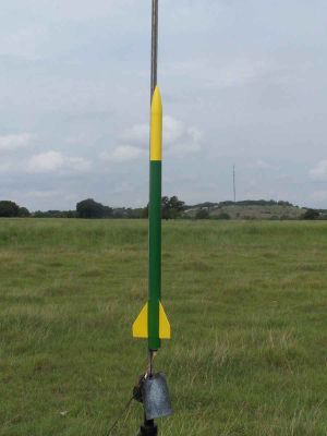
I pondered for a while what kind of paint scheme I was going to use. I looked through my rattle cans and saw two that had not been used before. One was John Deere green and the other was John Deere Yellow. That gave me an idea. I have a WCR Screamer I still sitting in the package. I decided to give this one a John Deere paint job, green with yellow trim and call it "John Deer". The other one will get the reverse paint job, yellow with green trim, and be called "Jane Doe".
I painted the yellow first, not paying attention to masking since all else would be covered by the green. I painted the nosecone, payload bay and fins yellow.
After the yellow had dried. I masked off the fins and the BT from the payload bay on up and hit it with the green. When the tape came off, it does look like something that belongs out at the ranch.
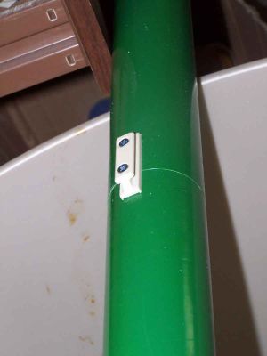
After the paint had dried, I used a razor to scrape away a line of paint coinciding with the tube couplers. I then used some sandpaper to rough up the bare patch. I mixed a small bit of 5 minute epoxy and applied it to the back of a Public Missiles linear rail lug. The lug was then pressed into place. As the epoxy was setting up, I further secured the lug with a pair of #6-1/2" flathead screws. I then considered the rocket to be ready for action.
Construction Rating: 3 out of 5
Flight:
The maiden flight of the Screamer II, AKA John Deere, was at the August 2008 Freedom Launch hosted by the Amateur
Rocketeers of Texas. Since I was pretty much on my own as far as determining a suitable motor, I looked to see what I
had. I came up with a Roadrunner F45-5.
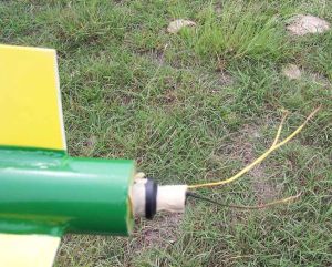
I loaded the rocket up on the rail, gave the warning, counted down and pushed the button. It immediately started up and then halted for just a moment before screaming skyward. I though that, perhaps, the launch rail had a kink in it but it was me that was kinked.
Although the rocket flew fine and high, a post-mortem revealed that I had messed up big time. In an effort to keep the igniter from slipping out, I often use a piece of tape. I did the same thing this time but with a difference. Without thinking, I taped an S-curve into the igniter and taped it firmly. When the rocket took off, it was trying to take the control wires along with it.
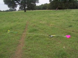
Still, the flight itself was a good one. It was straight and the rocket landed a reasonable distance away.
 The second flight was on a Roadrunner
G80-7. It was hooked up the same way but with much less tape to hold the igniter in place and put on the rail. When the
button was pushed, as far as I could tell the rocket simply ceased to be there. Others were tracking it however, and
began to express some concern that it would pass out of sight, even though it went straight up and the rocket is close
to 5 feet long. I got kind of miffed that I could not spot my own rocket and actually had time to start and complete a
few jokes before somebody said, "There it is!"
The second flight was on a Roadrunner
G80-7. It was hooked up the same way but with much less tape to hold the igniter in place and put on the rail. When the
button was pushed, as far as I could tell the rocket simply ceased to be there. Others were tracking it however, and
began to express some concern that it would pass out of sight, even though it went straight up and the rocket is close
to 5 feet long. I got kind of miffed that I could not spot my own rocket and actually had time to start and complete a
few jokes before somebody said, "There it is!"
I did manage to catch sight of it before it touched down. I was a long way away, almost out of bounds...on a G motor in a field that handles Js.
I didn't feel like so much exercise again that day so I put it away.
PROs: flies very well
CONs: none
Recovery:
The rocket came with a 24" ripstop nylon parachute. It was attached via 6' of elastic and 4' of Kevlar®
to the motor mount. I used a Nomex®
shield in place of wadding and the system worked well.
Flight Rating: 5 out of 5
Summary:
I think this is actually a pretty good rocket but I would not recommend it to anyone who has not built in this size
range before because of the inadequacy of the instructions. I think a reasonably competent person could figure it out
but it would be safer to do the learning with a smaller rocket or one with better instructions. Still, its a great
flier and I'm glad to have it.
Overall Rating: 4 out of 5
 |
 |