| Manufacturer: | Binder Design  |
The Rocket
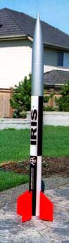
One of the highest flying, straightest trajectory and coolest Estes rockets I ever had was the "Iris". The medium body length and four big fins of this rocket resulted in one great flight after another. Scaled after an early 60's sounding rocket, Binder Design has another excellent kit for those that like to build sport replicas of the real thing.
 The Kit
The 4" rocket stands 70" and comes in excellent box packaging with a nice picture of the rocket on the outside. The kit includes the best instructions, illustrations and decals in the business. The body tubes and couplers are Kraft paper. The fins are 3/16" plywood that were without any warping at all. The kit also includes hardware (even a quick link) for the recovery system. The shock cord is some of that big black elastic that you find in your grandma's underpants (Scott, forgive me). So, unless your undergarments are suffering from structural failure, this part of the kit might be used to make a slingshot for your eight-year old.
The body tubes are marked but not slotted and there is an excellent guide and set of instructions to take care of this part of construction. Slotting the BT permits the installation of through the wall fin mounting. The centering rings and bulkheads are made from pressed composite material.
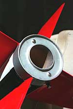
The original nosecone is an Ace product. For those of you not familiar with Ace NCs, the blow-molded product is somewhat flimsy, easily collapsing under the squeezing pressure of your hand. It also has a unique threaded male fixture on the bottom of the NC shoulder.
First Things First
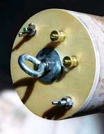
I decided that I wanted to use dual deployment for this kit so a few modifications were in order. I started by determining the body tube lengths that I would need to accommodate a drogue, an avionics bay and the main parachute. Although some folks are pretty good at using a rule of thumb for parachute space in a payload bay, I like to actually pack a representative recovery system. I used 20'and 15'of 9/16" tubular nylon shock cord, respectively, for the drogue and main bays as well as a Nomex® sleeve and 'chute protector for each section. A 24" drogue and a 58" main were packed into the bays as well. I figured each coupler and the nosecone would intrude into the parachute bays by 4". The resulting tube dimensions were 21" for the fin can, 13" for the drogue bay, 1 ½" for the avionics bay ring and 15 5/8" for the main bay. These dimensions were obviously influenced by the BTs that came with the kit and I wanted to stay true to the original rocket length. In reality, I could have reduced the overall tube lengths had I wanted to economize on length.
Fin Slots: The kit comes with a great template for locating the position of each fin. I used the template to double check the marked locations on the bottom of the fin can and then extended the line up the tube. I relied on a 3'piece of ¾" aluminum angle to make these lines. This little item has saved me a world of headaches and I would recommend it if you are having problems keeping lines true.
A little surgery with my Xacto blade knife and the job was done.
Fins: I put a ¾" bevel on the leading edge and a ½" bevel on the trailing edge of the fins using my trusty 1" belt sander. This little tool is a carryover from another expensive hobby of mine: golf. I used to constantly re-shaft golf clubs, make golf clubs, etc. but that's another story. I then lightly sanded the body of each fin with 100 grit sandpaper.
Fiberglassing: I also decided to 'glass the project to ensure a bit of durability. Keep in mind that 'glassing is not necessary for such a rocket. It will fly just fine with the stock tubes and couplers. I do it only to add to its life and maybe save me from making so many "wear and tear" repairs.
The body tubes received layers of 6 oz, 3.7 oz and a 2 oz layer of 'glass as a sanding veil. I hand laid the tubes using West Systems 105/206 marine epoxy. The fins were vacuum bagged with two layers of 6 oz glass and a 2 oz sanding veil. I use a 5 hp air compressor with a venturi attachment to draw the vacuum. I usually wait about a week after fiberglassing for a complete cure before moving ahead (but it isn't really necessary). I then used 220 grit to lightly, and I mean "lightly" sand the glass to remove dust, fuzzies, etc. and to generally "lightly" roughen up the surface. I always avoid sanding into the fiberglass weave. Why destroy the strength of this composite layer by cutting into a major component?
I used Bondo Spot Filler with a plastic spreader to fill any irregularities in both the body tubes and the fins. Lightly sanding with 320 wet sandpaper finishes the preparation. The wet paper does a nice job and doesn't clog like dry paper does. I used the Bondo because I had it. Lately, I have been using some Aeropoxy products that work very well and are probably better for epoxy laminated surfaces. I'll comment on those products in a future review.
A nice detailing step is the addition of two 1" rings near the top and the bottom of the rocket. These rings simulate component joints and are made from wrapping 7-8 wraps of 1" masking tape followed by 7-8 wraps of ¾" masking tape at selected locations on the body tubes. The relief provides a nice touch on the finished rocket.
 Motor Mount: This was my first experience
with the pressed material centering rings and bulkheads that came with the kit.
Although a bit skeptical, I decided to use them but did substitute wood for the
bulkhead on the zipperless design fin can and the bottom centering ring on the
motor mount tube. There can be quite a bit of stress on the eye bolt fastened
to the bulkhead on the fin can coupler; I didn't want to take any chances. The
bottom centering ring was replaced strictly to accommodate two #8 T-nuts that
will be used with screen door clips for positive motor retention. I felt that
the thicker wood would hold the T-nuts more securely. I placed stock centering
rings right at the top of the MMT where the leading edge of the fins would
contact the 54 mm tube and at the very top of the tube. I generally paint
viscous West Systems epoxy without filler on the contact points of each piece
of whatever I'm bonding. I then add a structural filler (milled fiberglass,
etc.) to my epoxy mix and use that to bond and to create a fillet for the
parts.
Motor Mount: This was my first experience
with the pressed material centering rings and bulkheads that came with the kit.
Although a bit skeptical, I decided to use them but did substitute wood for the
bulkhead on the zipperless design fin can and the bottom centering ring on the
motor mount tube. There can be quite a bit of stress on the eye bolt fastened
to the bulkhead on the fin can coupler; I didn't want to take any chances. The
bottom centering ring was replaced strictly to accommodate two #8 T-nuts that
will be used with screen door clips for positive motor retention. I felt that
the thicker wood would hold the T-nuts more securely. I placed stock centering
rings right at the top of the MMT where the leading edge of the fins would
contact the 54 mm tube and at the very top of the tube. I generally paint
viscous West Systems epoxy without filler on the contact points of each piece
of whatever I'm bonding. I then add a structural filler (milled fiberglass,
etc.) to my epoxy mix and use that to bond and to create a fillet for the
parts.
Hardware: I used ¼"-20 eye bolts for shock cord attachment points. These are stock stainless steel eyebolts from the hardware store. They are not forged; the eye is not welded or soldered back to the stem. With a rocket of this size and intended, I opted not to use forged material.
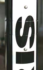
Painting: I used the paint scheme as recommended by the plans although from my readings there are several painting versions that have been used on the Iris. One touch that provided a different presentation of the rocket was to offset the alternating black/white quarters by 90 degrees. I thought that I had really discovered something unique when I saw this at a website and painted my rocket just like it. I later learned that the people painting for the Atlantic Corporation had applied the paint incorrectly. Oh, well.
My experience with painting has been limited to paint cans. Having tried Krylon, Rustoleum, Plasti-Kote and a couple of retail house brands, I favor Plasti-Kote "touch-up" automotive paint. Seems to be a bit more durable. And it applies very well over the venerable Kilz Brand primer. Kilz is highly recommended with its very high solids content.
 Assembly: For the most part, the component
parts went together nicely. I did have problems in two areas, however. The
first was the Ace nosecone. After talking to Scott Binder about it, Scott told
me he was aware of the issue and promptly replaced the 4" Ace NC with a
4" Aerotech nosecone. Much better. The second problem was the large
tolerance that existed in the coupler/body tube assembly. There was quite a bit
of play between the coupler and the body tube sliding over it. I painted one
coat of West epoxy on both the outside of the coupler and the inside of the
mating body tube and lightly sanded the two locations. The fit is much better
now.
Assembly: For the most part, the component
parts went together nicely. I did have problems in two areas, however. The
first was the Ace nosecone. After talking to Scott Binder about it, Scott told
me he was aware of the issue and promptly replaced the 4" Ace NC with a
4" Aerotech nosecone. Much better. The second problem was the large
tolerance that existed in the coupler/body tube assembly. There was quite a bit
of play between the coupler and the body tube sliding over it. I painted one
coat of West epoxy on both the outside of the coupler and the inside of the
mating body tube and lightly sanded the two locations. The fit is much better
now.
 There are a number of different methods of
attaching the avionics bay to the upper and lower parachute bays. Such methods
range from the "Stu Barrett" design, a single all-thread rod, two
all-thread rods fixed to a centering ring, PML plastic rivets, and so on.
Lately, I've been using #6 and #8 truss head Phillips screws fastening into
barrel nuts to secure the avionics bay to the parachute bays. I have been doing
this strictly for ease of assembly without regard to performance or impact on
the exterior aesthetics of the rocket. I used two screws to fasten each
parachute bay to the avionics bay. Keep in mind that other than under thrust
these components are not load bearing and the screws are used strictly to keep
the rocket components together.
There are a number of different methods of
attaching the avionics bay to the upper and lower parachute bays. Such methods
range from the "Stu Barrett" design, a single all-thread rod, two
all-thread rods fixed to a centering ring, PML plastic rivets, and so on.
Lately, I've been using #6 and #8 truss head Phillips screws fastening into
barrel nuts to secure the avionics bay to the parachute bays. I have been doing
this strictly for ease of assembly without regard to performance or impact on
the exterior aesthetics of the rocket. I used two screws to fasten each
parachute bay to the avionics bay. Keep in mind that other than under thrust
these components are not load bearing and the screws are used strictly to keep
the rocket components together.
The final touch is applying the cut vinyl decals. Peel off the protective paper on the adhesive side of the decals, rub a bit of a detergent and water solution on the target location, position and gently apply the decal. Apply pressure on the decal with a hand towel to secure it and you're done!
Summary
Nice rocket! I haven't flown the Iris yet but a June launch looks promising! I was thinking of an I-284 at Monroe and then maybe a J275 at Brothers later in the month. A quick Rocksim simulation shows 2400'with the I284 and 4600'with the J275. The kit comes with a more than adequate parachute that is sized for stock construction and flying. With my modifications, final parachute choices will be made once the rocket is weighed with Nomex® parachute protectors and the 9/16" tubular nylon shock cords. Probably a 24" drogue and a 58" Top Flight main will be used (just guessing).
Pros: Binder Design does an excellent job with items like the instructions, the decals, the component relief detail and the provision of options for construction. Based upon other Iris models that I have seen fly, this bird will fly well!
Cons: The Ace nosecone was a concern but, to be fair, I haven't flown a rocket with one. Cutting the fin slots may be a concern for some but it can be easily done with a bit of patience. An elastic shock cord may be a concern but please note that many kits fly just fine with the provided elastic. I have personal preference for tubular nylon and can't resist chiding Scott Binder on using elastic :)
This is a good 4" sport rocket for fliers relatively new to HPR or for experienced fliers looking for a sport rocket. I would highly recommend it to both groups.
Other Reviews
- Binder Design IRIS (54mm) By Francis I. Reachmack
Brief: Single motor, scale of early 60's sounding rocket. No special features, just for rocket launching fun! Construction: All aspects of packaging, instructions, illustrations, etc., were good. No problems understanding the construction process and building the kit. The one major glitch with the particular kit I received was the fins. Not only were all 4 (3/16 plywood) fins ...
 |
 |
Flights
|
|