| Construction Rating: | starstarstarstar_borderstar_border |
| Flight Rating: | starstarstarstarstar_border |
| Overall Rating: | starstarstarstarstar_border |
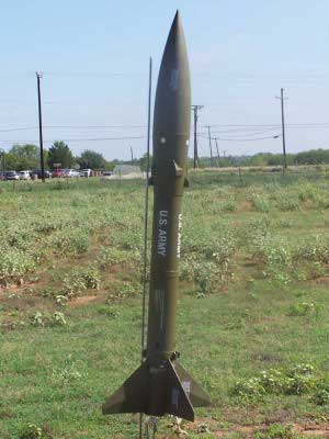
| Diameter: | 2.60 inches |
| Length: | 37.00 inches |
| Manufacturer: | Estes  |
| Skill Level: | 3 |
| Style: | Scale |
Brief:
This kit was an eBay find. It was already opened but all pieces were reportedly present. I took a chance and bid on
it, paid too much, and squealed with delight when it arrived.
Construction:
The Hojo starts, as do most kits, with the motor mount. A spacer is marked at 1/4" and used to push a thrust
ring into the motor tube. On inspection, I noticed that one end of the motor tube was ovaled but the other end was
round. I decided that the oval would not cause any problem if it were oriented forward so I inserted the thrust ring in
the opposite end.
The instructions then had me cut a slit for the engine hook. When I tried to cut at the mark I had made, I encountered resistance as the blade came into contact with the already mounted thrust ring. I moved the slit down just a bit and the resistance was gone. I then used a bit of tape to keep the hook from moving about for the next step.
Kits often have thin rings to slide over the engine hook and keep it in place. This kit goes a step farther and uses what Estes calls a BT-52 tube almost 4" long for the same purpose. A mark is made an inch from the end of the motor tube. The instructions indicate to apply a generous amount of glue is then applied along the hook from the mark to the forward end (even with the slit) and the BT-52 is slid over the hook.
Next, the cardboard centering rings are removed from their stack material and sanded to remove the attachment points. They are also checked to make sure that no sanding is needed to either fit around the motor tube or into the BT. Mine needed minimal sanding and just a little patience to work over the oval at the forward end.
The motor tube is marked in 2 places and the rings are slid on. The one with the slot in it goes forward. The rings were glued in place with yellow glue and filleted.
After letting the fillets set up for a couple of days ("She who must be obeyed" had some things for me to do), I marked the inside of the BT-80 for where the second ring was supposed to be. I gave both of the rings a bit of sanding to make them fit more smoothly and checked to make sure the fit was easy to position. I then smeared a ring of glue into the BT and shoved the motor tube in with just the first ring on the inside. I then swabbed another glue ring at the mark and pushed the assembly home. It went in easily, which can be a warning sign.
The instructions are very explicit about making a good seal around the things to prevent ejection gases from escaping. With that in mind, I placed generous fillets on the approachable faces of both rings and set the assembly to the side to dry.
About the time the glue had set up past the point of making any more changes, I noticed a blunder on my part. The forward centering ring had a slot in it intended to mount the shock cord. I was planning on making a loop of Kevlar® around the motor mount and then cutting a notch in the edge of the ring to pass the Kevlar® forward. Oops.
At this point I need to digress a bit and mention that in this model, Estes was providing nice 1/4" sewing elastic instead of the raw rubber band. That made for a pleasant but, now unrealizable, memory. Now back to our build...
Not quite believing what I was doing, I found myself cutting a long length of the heavier Kevlar® and tying a loop in the middle. I then used an Estes "Safe Rocketry" brochure to construct an oversize tri-fold. The mount I constructed had both ends of the Kevlar® glued in. The loop for attachment is in the middle. I also made a fairly wide mount to distribute the stresses over a greater area. I installed the mount with yellow glue.
The next step is to apply the circumferential bands around the BT. The kit comes with a sheet of heavy cardstock, some of which is used for templates and some which is used to form these bands. There are 3. Each is placed on top of the previous making the whole the thickness of triple cardstock. They are applied with yellow glue and the instructions indicate that the ends should not line up over each other. The first two bands are plain and the third has a line of circles on it which are supposed to be cut out.
I applied the 2 bands without any problem but was at a loss as to how to punch the needed holes in the third. I decided to investigate a hole punch at home later on and skipped to the next step.
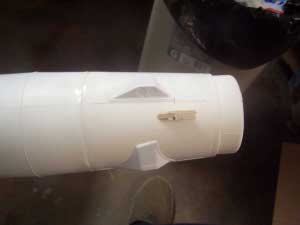
The nosecone is plastic, as is the fin can, the fins, and another part I will call the nosecone base. The NC base and fin can are cast as a single unit. The instructions had me saw the 2 pieces apart. I then used a bench sander to take the plastic down to where it was supposed to be. His involved about 1/16" on both pieces.
The instructions say to use a razor knife to drill 2 holes in the NC base. That seemed entirely too much effort when I noticed that I had forgotten to put my power drill away a few days ago and that drilled the holes nicely. I then passed one of the pieces of sewing elastic provided through the holes and then tied the ends together, forming a single large loop. This is supposed to be the shock mount for the NC. The NC base was then glued into the NC after sanding the edges down a little.
Next up were the fins. This is my first attempt to work with vacuformed plastic. While I see the advantages, at this point I am not a fan.
There are 4 fins and each fin comes in 2 halves. A razor is used to score a line between the parts and then the plastic is folded to snap apart. This actually worked well for me. I had thought that the plastic would be thinner.
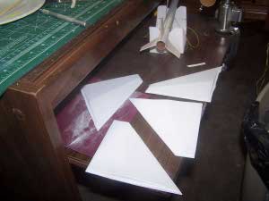
The fins then needed to be cut down to size. You are supposed to score and snap leaving about 1/8" of excess material. This probably would have been fairly easy if each edge of the fins were straight. One edge is not straight. That made my life more difficult. I finally settled on using by bench sander to remover material to within the given margins. I cleaned up the edges with a razor and some hand sanding also.
In instructions indicated that I should use a piece of 100-150 grit sandpaper to thin the edges to about half their original thickness. This was done with unknown effects on the efficacy of putting the things together.
Liquid plastic cement was used to join the 2 halves. There are no guiding lips or alignment holes. Everything is done by eyeball and hoping for the best. These parts are then set aside to dry.
When I got around to working on the third circumferential band, I thought I would use a hole punch to make nice and even little hole. When I checked, though, the holes would have been too large. As I was returning the hole punch to the drawer, I noticed a leather punch with multiple spikes for assorted hole sizes. On checking it out further. I found that the largest of the spikes was just the right size. After that, punching the holes was not a problem although I did have to stop and clear out the "chads" every now and then. Once the holes were punched, I cut the band out and glued it over the previous two.
I have to admit right here that working on the fins has been the most tedious part of this build. After getting the two vacuformed halves together to make 4 fins, there was still a lot of sanding, filling, sanding, trimming, sanding, cursing, sanding, re-gluing, and sanding to be done. The material from which the fins were formed has to be removed right up to the edge of the profile. On the straight sides this is not too bad but along the root edge it becomes much more complex. There is a piece that hangs over the top of the fin into a depression. The fin needs to sit flush and straight. Sometimes the removal of material opens up a cavity that needs to be filled. It seemed to go on forever.
The process was basically this: I trimmed off as much as I could with a razor knife, used a sanding belt to remove material to as close to the fin as I dared, hand sanded to remove burrs, sharp edges, etc., filled cavities with green Squadron putty, sanded some more and test fit some more. I finally reached the point where my "enjoyment" was decreasing to a level incommensurate with a "hobby" and figured it was good enough.
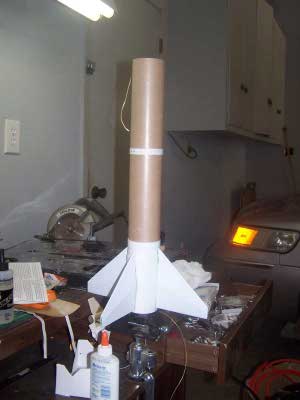
The fins are supposed to be mounted on the fin can with plastic cement. In the past, my luck with this stuff on fins has not been too good. This is true of both the tube type and the liquid solvent. I decided to fit these fins with 5 minute epoxy. I mixed the epoxy in small batches, each just big enough for one fin. I then applied it to the root edge and pressed the fin to the fin can. The front of the fin fits into a little indent which helps but is not enough to really make sure they will all line up together. Most of the fin is centered on a mold line on the fin can. The epoxy method seemed to work well. After each fin was done, I went on to the next one, eyeballing things along the way to make sure they were straight.
Mounting the fin can to the body tube posed no problems at all. The instructions indicated that the joint was to be made with tube type plastic cement but I elected to use 5-minute epoxy again. The fit was rather loose so no sanding was needed. I mixed a small amount of epoxy, spread it in a ring around the inside of the BT, and slipped it on. I checked the aft end to make sure the motor tube was centered and it was as simple as that.
After dealing with the fins, I was not too enthusiastic about working with the spin motors which came on the same vacuformed material as the fins but they did not turn out to be too difficult. On the first motor, the excess material was trimmed away by scoring and snapping of the plastic. I then sanded down to the change in contour. For the other three, I followed a similar procedure but with an important difference. I tried to score a line right where the material transitioned from flat to profile and then use the excess material as a handle to snap it off. That worked well and I was left with only minor sanding.
The result of the previous step was a series of 4 spin motors which looked fairly nice but which had flat bottoms needing attachment to a round nosecone. To rectify this, I used the procedure spelled out in the instructions to good effect. I wrapped a piece of #100 sandpaper around the NC where the spin motors were to me mounted and then rubbed the motors back and forth to achieve the desired profile.
Each of the spin motors was attached to the NC along a line molded into the plastic of the NC and 1" up from the bottom. I used the liquid plastic cement for this and it seemed to make a good join.
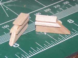
The kit comes with a strip of thin balsa and a small sheet of thicker balsa. This is used along with the provided templates to cut a bunch of small parts that are used for detailing and offsetting the launch lugs. I expected this to be rather tedious but it did not turn out to be so.
For the thick balsa, there was just a single template for the two different types of parts. Two copies were needed of one part and four of the other. I cut the template out with scissors and transferred the lines to the balsa, noting the orientation of the grain was compliant with the directions. Once the parts were marked, I used a razor and straightedge to cut them out.
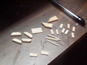
 The thin sheet had enough template for each of the parts to be cut. I taped the
template to the balsa strip at a place where the tape was smaller than the part being cut and then proceeded to slice
the parts off.
The thin sheet had enough template for each of the parts to be cut. I taped the
template to the balsa strip at a place where the tape was smaller than the part being cut and then proceeded to slice
the parts off.
After the pieces were cut out, it was fairly simple to glue them together. A pair of skinny bands was glued to either side of the fin-looking things. When the glue was dry, the excess overhang was cut off and the edges sanded. A cover plate was then glued on top. When that glue was dry, it was sanded to conform with the rest of the bevel.
A similar but wider assembly was put together for the lower portion of the rocket in the same manner.
And finally, two more things were made which each resemble half of the previous thing. All of these things are referred to as launch shoes in the directions.
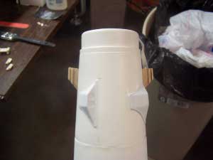
The launch shoes for the nose cone are mounted on opposite sides, 180 degrees from each other. The kit provides a bulb of cement with which to do this but I opted to use epoxy.
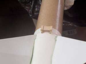
The lower launch shoes will not fit right on the rocket without sanding the profile of the BT into the assemblies. Accordingly, the BT was wrapped with #100 and the curve was sanded into the mounting surfaces.
I decided to use epoxy again to mount the lower shoes but there was some confusion in my mind as to exactly where they were to go. Both assemblies are mounted 180 decrees apart and centered between the fins but my problem was in locating them fore and aft. They seemed like a natural to be glued directly to the BT but the drawing in the instructions clearly shows them mounted on the plastic fin can, protruding to the level of the fins. That leaves a bit hanging off. Even so, that is where I epoxied them.
PROs: straightforward and mildly challenging, nice looking
CONs: none
Finishing:
The finishing of the Hojo started off with a coating of Kilz. This filled mostly the balsa, covered up the writing,
and gave a bland, flat white surface. When the Kilz had dried, I gave the entire rocket a gentle sanding. The entire
rocket was painted with Testor's olive drab. It took 2 cans.
For me, the biggest disappointment with this old kit was the decals. There weren't any. Instead, I got some crack and peel stickers. This surprised me for a couple of reasons. First off, I expect the upper level Estes kits to have a higher quality. Crack and Peel makes sense for RTF Walmart kits but not for something like this. Secondly, the instruction specifically make reference to, presumably, waterslide decals. There is a warning to let each decal set completely before starting the next so that they do not slide out of place. Crack and Peels do not slide around.
I remember thinking that the "decals" seemed kind of thick but my brain was just barely turning over. I cut out the first one and set it in a bowl of warm water. After a while, I noticed that it was just sitting flat on top of the water instead of curling up like the water slides usually do. I pulled it out of the water and looked more closely at the master sheet from which it had come. Sure enough, it was crack and peel.
Fortunately for me, the first sticker was not damaged. I proceeded to place the stickers as instructed as sat back to admire my flat painted rocket with all of those high gloss stickers.
PROs: Easy
CONs: stickers instead of decals
Construction Rating: 3 out of 5
Flight and Recovery:
The day finally came for me to launch this one and I was jazzed. I selected a D12-3, inserted about a dozen pieces of
wadding, and then prepped the chutes.
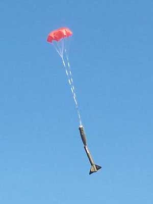
I should mention here that the model is intended to come down in 2 sections, each with its own chute. I'd rather keep it all together. I fashioned a Kevlar® harness and then used sewing elastic to connect the NC to the harness. I also used two 18" nylon chutes. Each was connected to the harness with about 4' of sewing elastic.
The liftoff was as slow and dramatic as promised. It flew straight and true and blew the NC at apogee. It wasn't all that high but it was beautiful. It drifted down gently under the tandem chutes.
For the second flight, I decided to go with an AT E15-4. The rocket was set up the same way as before and everybody pause to watch. At ignition, there was some chuffing and I had just come to the conclusion that it wouldn't go off when it did. It was not as slow as before but it was a great flight straight up.
It hit apogee and started to turn down. After all, it had an extra second to work with. It kept coming down, faster and faster. Unless my eyes deceived me, it was accelerating at about 32 ft/sec^2. Finally, about 100 feet up, it ejected and everything deployed normally. Upon inspection of the bag the motor came in, it turned out to have a 7 second delay and not 4. I had it stashed in the wrong bin.
PROs: Beautiful straight flights, awesome liftoffs
CONs: none
Flight Rating: 4 out of 5
Summary:
This is a nice rocket marred primarily by the crack and peel stickers instead of decals. I still like it though and
am glad to have it in the fleet.
Overall Rating: 4 out of 5
Other Reviews
- Estes Maxi Honest John By Robert Tung
This is a good kit! You have to make sure you glue the fins on good or it won't be a stable flight! The kit contains: 1 body tube 1 nose cone 2 sets of plastic molded fins 1 boat tail 1 nose cone tail The instructions were very good and easy to follow. It was hard to make the fins stick onto the rocket. Finishing: I forgot to add glue fillets to the body tube to get ...
- Estes Maxi Honest John By John Lee
Brief: This is a re-release of the early 80's Estes kit. A 1/9th scale model of the famous U.S. Army surface-to-surface, supersonic ballistic missile. This highly detailed model comes with pre-shaped, accurately scaled fins and molded plastic nose cone. Spectacular recovery with giant, dual 24" parachutes. It makes an impressive display model. Construction: This is the Maxi ...
 |
 |
Flights
|
|