Estes Pro Series 1 Jayhawk
By Lester Anderson
2014-11-29
I am building up an Ebay find. This is a 1/5 scale model of the Jay Hawk Supersonic target drone of the 1960's and 1970's. It is about the same size as the current Mad Cow Jay Hawk kit, 2.5 in dia. body tube for the Estes vs. 2.6 in dia. for the Mad Cow.
Parts
2014-11-29
As can usually be expected with an open EBay buy, parts were missing. I ended up having to re-cut all the centering rings, because the originals were not included. I also had to re-cut the rudder fins, also missing. To my good fortune, there was a lot of wasted space on the wing sheets. I moved the "ailerons" to a different spot, and cut 2 pieces of rudder from each existing sheet, still leaving enough balsa to re-cut the ailerons also. Thank goodness for YORP, which has the instructions, fins, and decals all scanned in a pdf file.(http://www.oldrocketplans.com/estes/est2085/est2085.pdf) Other than that, it is what you might normally expect from 20 year old parts. The glassine has yellowed, as has the nose cone. The vacuum formed parts still look good. And the existing balsa was still straight.
Engine mount and boat tail
2014-11-30
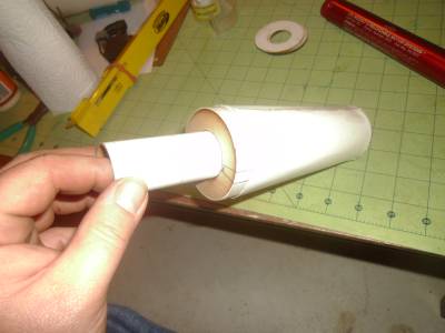
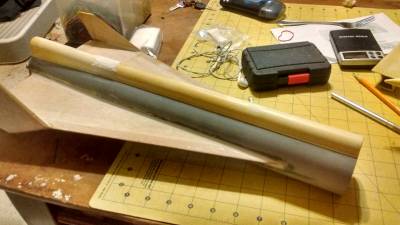
The instructions start by having you make the aft boat tail. It is a simple paper transition glued to itself. It was also one of the pieces not included in the EBay parts, so I ended up having to cut out a replacement from some poster board I had laying around. I double layered it for making a even seam on the outside, and a slight increase in strength.
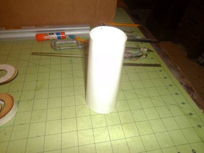
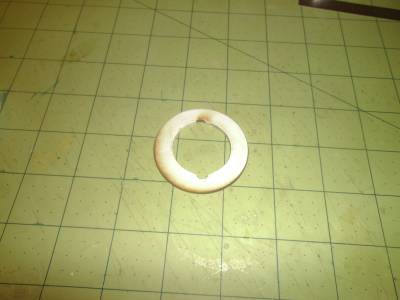
Next comes some minor upgrades. Being as all the existing centering rings were missing, I needed to make new ones. This was accomplished by drawing them up with Autodesk's design program 123D Beta 9. Autodesk does not support this anymore, but it is the most versatile 2 and 3D design program I have found for the freeness of it. After the drawing was done, I took the design (converted into a PDF file on a flash drive) to my local FabLab to use their laser cutter. Wonderful tool, made parts that were perfect the first time.
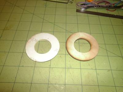
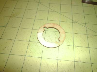
I also made a retainer ring to help hold the engine hooks in place. This used to be the 24mm aft centering ring, which I repurposed. I decided to upgrade to a 29mm motor mount.
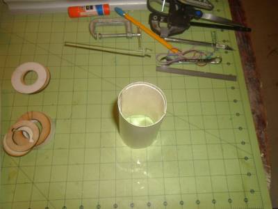
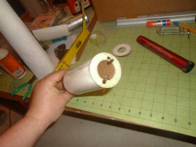
Next, I dry fit everything together to see if it still looked right.

Next we move on to gluing it all together.
Motor mount assy.
2015-01-13
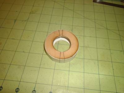
Well, now that the holidays are over, it is time to add more entry's to this build. We left off with dry fitting all the motor mount pieces together. Next came gluing it up. I used Gorilla brand wood glue. I only plan on launching this on a 29mm G engine at the most, so I figured with 2 plywood centering rings backed up by 2 Bristol board centering rings, I believe I have plenty of surface area to grip to.
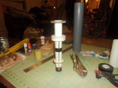
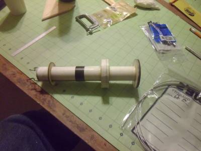
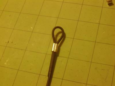
Next we need to attach a shock cord anchor to this beast. I used 1/16 galvanized braded steel cable from my local Lowe's hardware store, secured with a couple compression fittings. The cable was covered with electrical heat shrink tubing to prevent the cable from snagging on my shock cord or parachute.
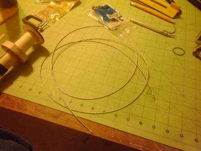
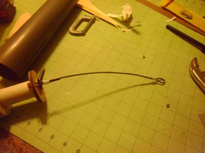
The base of the anchor has a piece of 3/16 dowel wrapped in about 8 layers of aluminum foil tape to spread out the ejection forces on the centering ring. The dowel is secured with a little more aluminum tape.
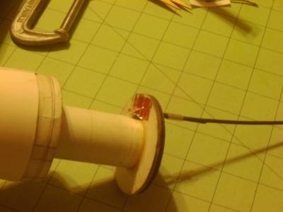
All that's left is to glue on the aft boat tail, then glue it into the body tube.
The aft tail cone has a few ripples from where the rubber bands held it together while the glue dried. I will be filling all that with some wood filler and sanding it smooth.

Fins
2015-01-13
Ok, I admit it. Over the holiday's I did some work and forgot to take pictures. I ended up almost completely working the fins to completion before taking any pictures.
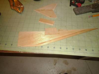
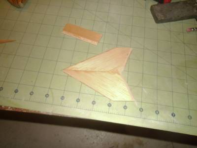
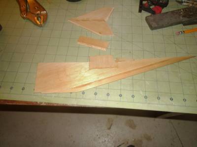
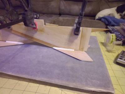
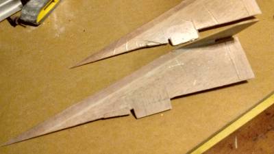
This would be the Rudders, ailerons, and main wings. As you may notice, the wings are 4 different pieces of wood. The "thru the wall" tabs are from the fin sheet, locking into the motor mount assy. The leading edge is a piece of model airplane trailing edge stock, which the instructions have the mating surface sanded to make it "arrow" shaped. This way, there is an equal bevel on top and bottom of the wing when it is glued on.
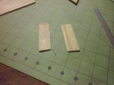
Next are the Rudders. These are 2 piece assembly's. Glued together at the root edge, and beveled at the leading and trailing edges to a 45 degree angle. I found the easiest way to get the 45 degree angle was to stack the fins together with a 1 material thickness space on the leading edge, then sand a surface across the exposed edges till smooth. The leading edge is easier than the trailing edge because of the included angle on the trailing edge.
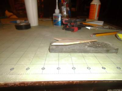
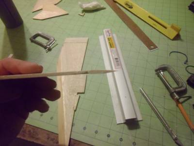
And the ailerons. Kind of small, and difficult to contour correctly.
These ailerons have the wrong profile on them. They were too short to properly bevel the leading edge to a 60 degree angle. That same shortness prevented me from beveling the trailing edge at an even taper from the front bevel to the trailing edge. My solution was to re-sand the leading edges to a sharper angle, assemble the ailerons to the wings, then sand the trailing edges to a finer taper.
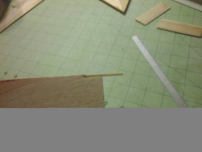
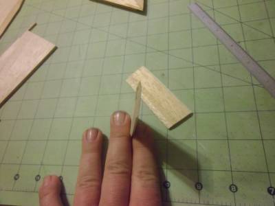
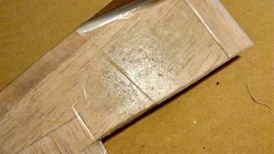
The first picture here is of a detail on the outer edge of the wing. It is simply a match stick glued into the factory cut edge. It's purpose is to hold he aileron in place while the fin is being assembled. The only other gluing surface for the aileron is the aft tail cone, because of the sharpness of the aileron's leading edge. I plan on laminating the entire wing assembly with paper and epoxy for strength next.
Wing & rudder assy.
2015-04-18
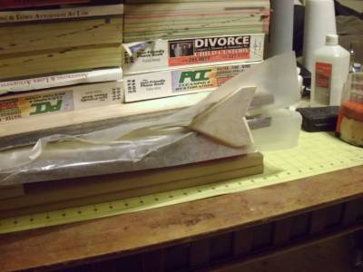
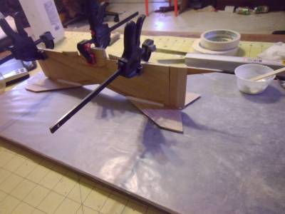
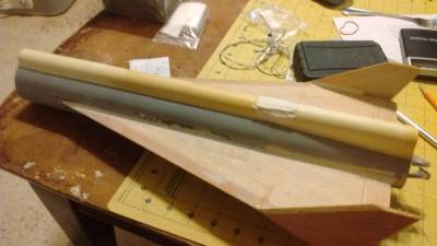
Just a couple pictures of the main wing assy. I used a little thin CA to tack the rudders to the end of the wings, then some epoxy mixed with microballoons to fillet the joint. Next, laminating the wings with paper and epoxy for strength.

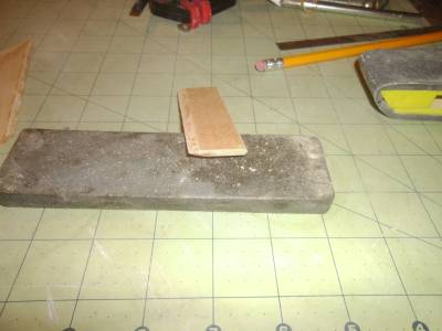
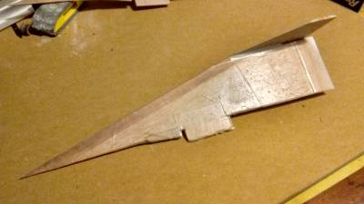
a little bit of detail from the fins. One has been sanded, the other has not.
Fin and body attachment
2015-05-17
Wings / fins are now epoxied to the main body tube. The fillet's need some touch up sanding, as do the tips of the rudders.
. .
. 
Equipment bay
2015-07-15
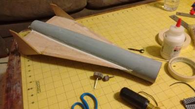
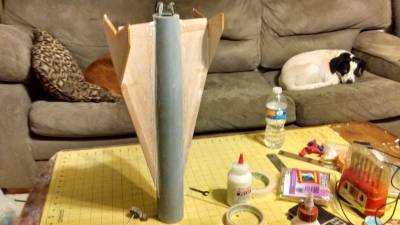
Finally got back to building this. I glued the bottom blow molded equipment trough to the main body. I'm still debating with myself if I want to add fillet's to smooth out the bottom edge of this decoration.
Nose cone.
2015-07-24
This nose cone takes a bit of work to put together for this model. It has antennae the glue to it, the leading edge of the equipment Bay, and the two elevators that the original missile had. I started by gluing the antennas on to it.

Next, I glued on the forward end of the equipment Bay with thin CA glue.
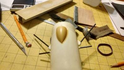
And lastly we go on the elevators. These were two piece Affairs that needed to be glued together before they were attached to the nose cone. Due to every other review that I had seen showing that these elevators were a weak point of the nose, they are completely filled with West systems epoxy for gluing onto the tabs that they hold on to. Even the inside of the tabs was filled with epoxy.
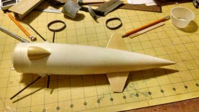
All that's left now is to smooth everything out in prep for primer.
Painting and Decals
2015-08-09
well I didn't take any pictures between primer and paint. Sorry about that for those of you have been watching. All in all the paint turned out pretty good this time.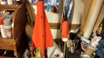
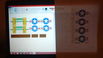
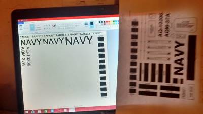
I also decided to redraw all the decals. The scans provided by The Olde Rocket Plans took up a lot of space on a 8.5x11 sheet of paper.

Last Entry
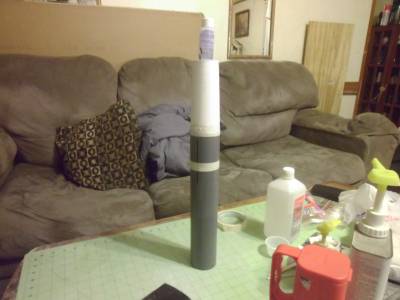
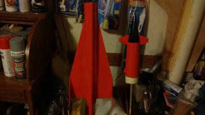
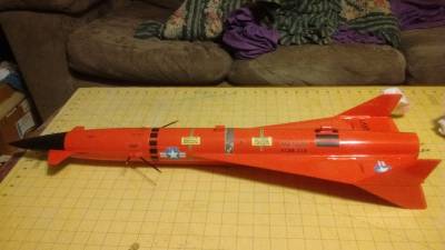
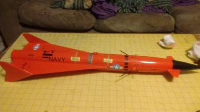
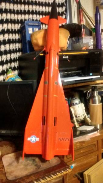
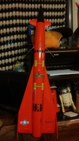
2015-08-29
well well this entry is finally done. It's taken me the longest of any model to build this Jayhawk. This is a primary reason I don't do scale models because they do not fascinate me. So here are some pictures to show it is complete.
 |
 |