Fat Cat Rockets I.P.F.I. Strikeship
Fat Cat Rockets - I.P.F.I. Strikeship {Kit}
Contributed by David Fergus
| Construction Rating: | starstarstarstarstar |
| Flight Rating: | starstarstarstarstar |
| Overall Rating: | starstarstarstarstar |
| Manufacturer: | Fat Cat Rockets |
 Summary:
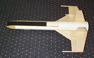
A fantasy futuristic single pilot space fighter. It has a unique fuselage
shape, flies on 29mm motors (F50 is the only motor recommended by the kit
maker) and has rear ejection parachute recovery. This rocket was named in a
contest sponsored by EMRR. The name was a combination of the top three vote
getters with IPFI being the abbreviation for InterPlanetary Fighter
Interceptor, Strikeship the operational usage, and Lightning it’s
nickname. It joins other kits in the Fat Cat space fleet (P.T.S. Shaman and
O.G.M. Roanoke)
PRO: unique design, quality components, and stable flight on an F50.
CON: none
CONSTRUCTION:
The kit came in a cardboard box from the manufacturer with sub-kits of groups
of components in separate sealed plastic bags. All of the components were
present, and there was no damage. Even though this is a unique design, it was
accomplished using standard components common to the rocket kit industry. The
imagination behind this design is to be commended! The instructions are printed
on four double-sided pages using a 4-color ink jet printer. Each step has
explanatory diagrams with notes and arrows. Two pages are devoted to finishing
suggestions and decal location guides. The instructions are adequate for an
experienced mid-power modeler. However, novices to mid-power should probably
make this kit a later addition to their fleet after they have built several
mid-power kits. A few notes that I made while assembling are added here as
additional comments for future builders, and not as criticism of the kit maker.
 |
 |
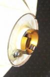
Step 1: Assembly of the engine mount: If you wish to add positive engine retention, you should do so at this step prior to assembly. I put a retention clip in one end of the motor mount for when I use an RMS motor and left the other (flush) end free for friction retention of SU motors. I also soaked in some CA into the inside of the motor tubes at both ends which makes the motor tube less likely to wear after numerous launches and make the motor tube easier to clean after a launch.
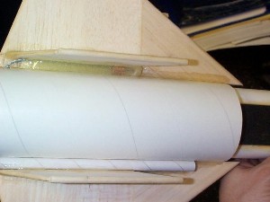
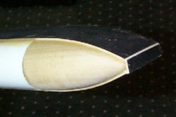
Step 2: Assembly of the forward fuselage: When gluing the two body tubes together, minimize the glue in the rear 1.5 inches until after the centering rings are installed. I did not, and it was harder to install the forward centering ring without a lot of sanding to get it to fit over a healthy glue fillet. There is a possible “gotcha“ in this step. In Step 2, make sure you line up the two centering rings so that the front fuselage will be parallel to the rear fuselage when assembled. The two centering rings have two side-by-side holes cut for the inner parallel body tubes. These two holes on the two centering rings were cut so that the distance from the edge of the hole to the outside of the centering ring was slightly different on one side compared to the other. I did not realize this till after they were glued on the body tubes, and the 50-50-90 rule (If given a 50-50 chance of getting something wrong, you will get it wrong 90% of the time) came into effect so that the two centering rings did not match exactly in their orientation when glued onto the body tubes. If not caught, it would have resulted in gluing the forward fuselage into the rear fuselage in Step 10 and having a slightly crooked rocket. I caught this before gluing, and used a long length of 3” quantum tube as an alignment reference tool to test-fit and sand the opposite outside edges of the two centering rings to ensure parallel alignment of the forward fuselage to the rear fuselage.
 Step 3: Do not glue the two body
halves together now! That is done in Step 10. I didn’t read this step #3A
carefully enough and actually glued the rear body tube to the front fuselage
assembly here. It did not ruin the kit to do this, but it was inconvenient in a
few of the following steps.
Step 3: Do not glue the two body
halves together now! That is done in Step 10. I didn’t read this step #3A
carefully enough and actually glued the rear body tube to the front fuselage
assembly here. It did not ruin the kit to do this, but it was inconvenient in a
few of the following steps.
Step 4: Sub-step C says to seal the leading edges of the wings, fins and rudders with CA. I did the trailing edges as well.
Step 5: To attach the wings to the body tube, the instructions say to rough up the surface with sandpaper to create a better bonding surface. I attached the wings with outdoor wood glue and later filleted with 30 minute epoxy. Note that you should wait to fillet till after step 6 when you attach the fins and rudders.
 Step 6: To fillet with 30 min epoxy, I used
Popsicle sticks to get an even concave fillet and a damp paper towel to wipe up
excess. Don’t forget to fillet the wing joints too.
Step 6: To fillet with 30 min epoxy, I used
Popsicle sticks to get an even concave fillet and a damp paper towel to wipe up
excess. Don’t forget to fillet the wing joints too.
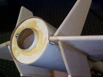
Step 7: To attach the metal shock cord anchor, an epoxy block is built up with about five applications of 5 minute epoxy. The dams at the front and back of the lower fin worked pretty well, but did not create a faired shape. I let the last application spill over and make more of an aerodynamic shape at the front of this fillet. I also put a blob of epoxy on both of the copper clips, and also dipped the loop of steel leader in epoxy to make it less abrasive to the eventual attachment of the elastic shock cord. The diagram in the instructions show the launch lug being shorter than the lower fin, but the launch lug provided in my kit was longer than the fin. Either is OK. The notch cut in the rear of the body tube to accommodate the wire shock cord leader should be reinforced with CA for wear resistance. I also put a small radius in the notch to allow the wire leader to smoothly transition in and out of this notch.
Step 8&9: straightforward, no comments.
 Step 10: Here is the step that I did way
back after Step 2 because I didn’t flip the page first before doing what I
assumed was the next step. I built the rest of the model around an already
assembled fuselage. Not a big deal, except the nose is heavy from all the nose
weight, and it makes it slightly awkward to handle. Make sure the centering
rings fit up and actually cause the two sections of fuselage to mate in a
parallel line. Sand as necessary to ensure this.
Step 10: Here is the step that I did way
back after Step 2 because I didn’t flip the page first before doing what I
assumed was the next step. I built the rest of the model around an already
assembled fuselage. Not a big deal, except the nose is heavy from all the nose
weight, and it makes it slightly awkward to handle. Make sure the centering
rings fit up and actually cause the two sections of fuselage to mate in a
parallel line. Sand as necessary to ensure this.
FINISHING:
The spiral grooves are pretty big in the provided tubes so some application of
Elmer’s F&F is required. The balsa, though very impressively thick,
has fairly large grain, which also needs to be filled. Two pages of diagrams
are provided which show two suggested paint and decal schemes. Page 1 of the
finish pages also shows the recommended balance point with the motor installed.
If too far back, the kit maker suggested by phone consult adding more nose
weight by pouring lead shot into both forward tubes and covering with epoxy.
The web site lists the weight of this finished rocket as 20oz. My finished
rocket only weighs 16 oz, but I used healthy epoxy fillets everywhere. It
worried me a little that my rocket might not be as sturdy as the kit
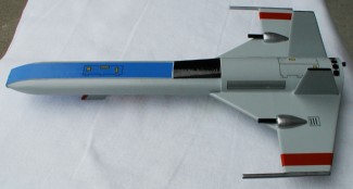
makers’ version, but it feels solid and well-built. I chose to paint the
rocket Krylon pearl gray which I felt would be a realistic space fighter color.
I have yet to add highlights and attach the decals, so I will send a picture to
Nick at some future time. The web site for the kit maker does provide pictures
of various paint schemes customers have used. One intriguing scheme is this
rocket decked out in police cruiser colors using decals from a Radio Controlled
car kit.
 FLIGHT:
The instructions list only one engine as recommended; an F50-5. I contacted the
kit maker and asked him about this. I pointed out that Aerotech had a F50-4,
F50-6, and a F52-5, but no F50-5. He agreed and said that any of those motors
should be fine.
 So far, I have only
flown the rocket on an F50-4 single use, and it is a good choice. To use an RMS
casing, there is room in the motor mount, but less expansion volume in front of
the engine than with an F size SU motor, which might lead to a more violent
rear ejection than with a single use motor (theory only, not confirmed at this
time). I have not tried an RMS motor yet, but intend to.
So far, I have only
flown the rocket on an F50-4 single use, and it is a good choice. To use an RMS
casing, there is room in the motor mount, but less expansion volume in front of
the engine than with an F size SU motor, which might lead to a more violent
rear ejection than with a single use motor (theory only, not confirmed at this
time). I have not tried an RMS motor yet, but intend to.
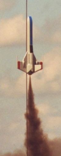
Flight on an Aerotech F50-4T single use motor was straight and stable to somewhere between 500 and 1000 ft. My calibrated altitude eye just wasn’t up to a more accurate altitude estimate that day. I wish the kit maker had given an estimated predicted altitude in the instructions, just to give me an idea how high to expect on the recommended engine, but with his weight so much different than mine, it would only be a rough estimate anyway. I may have to someday get out my trusty Estes Altitrack and see what I get for altitude.
RECOVERY:
The provided 24” nylon chute is a good choice and the rocket came down
gently to a soft landing at the sod farm.
OVERALL:
Everything considered, it is a good kit that uses a unique design concept and
excellent materials. It is stable and recovers reliably. I like the
comprehensive decal set, and some of the extra details such as the wooden gun
mounts on each wing, and the landing strut for display (removed for flight).
RATINGS:
Construction:
5
out of 5, Flight/Recovery:
5
out of 5, Overall:
5
out of 5
Other Reviews
- Fat Cat Rockets I.P.F.I. Strikeship By Nick Esselman
After holding the Fat Cat's Name This Rocket and Story Contest over this sleek, futuristic looking rocket, I decided to purchase one at Fat Cat's special introductory price. You should check out the contest stories. They are great. Fat Cat's decided to combine the suggested names from the top three winners and came up with the I.P.F.I. Strikeship "Lightning". I call it the Strikeship for short. ...
 |
 |