
 Brief:
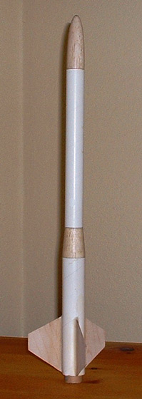
Sport rocket with pass-through transition. This is a clone of FSI's third rocket model as it appeared during the first half of the 1970's.
Construction:
The following parts were all obtained from Semroc Astronautics:
- ST-1160 (6") - lower body tube
- ST-8F90 (9" cut to 8") - upper body tube
- ST-940 (4") - motor tube
- BC-8F28 - balsa nose cone
- BR-8F11 - balsa transition (1")
- CR-9115 - centering rings (2 needed)
- TR-9 - motor block
- LL-117 - 1/8" x 1.75" launch lug
- ST-545 - transition support (4.5")
- EH-38 - long motor clip (3.5")
- HTC-8F - motor spacer
- CP-12BW - 12" plastic parachute kit (blue/white)
I also supplied other parts from miscellaneous sources:
- 100# Kevlar cord - shock cord anchor, about 12" (BRS Hobbies)
- 1/4" flat braided elastic - shock cord, about 42" (Wal-Mart)
- small screw eye
- 5/8" dia. fender washers (2) - nose weight (hardware store)
- 1/16" aircraft plywood - fin stock (BalsaUSA)
- #5 split ring (fishing store)
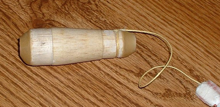 The nose cone and transition originally used by FSI were turned from hardwood, but Semroc's versions of these parts are made from balsa. Also of note is that FSI's transition came with a large hole bored through the middle, while Semroc's version of the same part is solid. Finally, instead of purchasing the parts for the motor mount separately, as noted above, you can now simply purchase Semroc's engine mount kit, EM-9115. (This mount kit was not yet available when I built my model.)
Flight Systems, Inc. opened for business in 1967, the same year that I got into model rocketry. During my initial 4-year run in the hobby, I never heard of them. Which is too bad, because the company is fondly remembered by many sport rocketeers who, over the next three decades, were more inquisitive (and more daring) than I was. A couple of years after returning to the hobby, I finally discovered the company through the archive of FSI catalogs at Sven Knudson's Ninfinger model rocketry web site, and through the collection of kit plans posted at Scott Hansen's Ye Olde Rocketry Plans web site. Although this company is mostly remembered for their line of mid-power black powder rocket motors, I was taken by the clean lines and simple elegance f their kit designs. I was also just getting into cloning at about that time, in order to be able to experience all the great rocket designs that had come and gone during my 33-year hiatus from the hobby. I really wanted to try to build reproductions of at least some of the FSI designs, but I knew that it would be a tall order, since their kits used many non-standard parts. Then I found out that Semroc Astronautics was adding FSI-compatible components to its ever-growing catalog of reproduction parts. And so, exactly two years ago, in November 2006, I set a personal goal of cloning every single one of the 30 rocket designs that FSI sold as kits during its 26-year run. I originally set myself the goal of building them all within one year, but that deadline has slipped quite a bit since then, and now I don't have any fixed timeline for finishing them all.
The first design that I decided to reproduce was the Nova, kit number MRK-III. The Nova was one of the small number of kits that were listed in every FSI catalog from 1967 to 1994. Like many of FSI's other kits, the exact dimensions of this model changed over the course of its run, by increasing in length as the years progressed. In the Nova's case, almost all of these modifications came in the first few years, and by 1971, it seems to have settled on its "classic" dimensions, with an overall length of a (nominal) 18 inches. The 1971 design, shown in the beautifully hand-drawn and hand-lettered "catalog" from that year, is the version that I reproduced.
I used the instructions available at Ye Olde Rocketry Plans FSI Mark-III as a guide to building the Nova. The first thing I noticed about the plans, which appeared to date from the early 1970's, was that they were entirely hand-lettered in a calligraphic (but readable) style. The second thing was that there was only one large cut-away and profusely labeled illustration ("artistically" drawn, as opposed to being conventionally drafted) of the assembled rocket to accompany the text and depict the assembly process. There were four additional detail illustrations inside "balloons" on the same page that show a few specific steps. Finally, there was no detailed parts list. Instead, there was another illustration in the lower left hand corner of the page that contained little hand-drawn and labeled pictures of the kit's parts. The plans at YORP do contain a very helpful addendum listing the dimensions and part numbers for the key components. I also consulted the various parts pages at Semroc's website, studied the components pages in the posted FSI catalogs, and also found this enormously helpful cross-reference chart at Semroc's website. With the help of these resources, I was able to order the proper parts and proceed with the build with a reasonable degree of confidence.
I used Aleen's Quick-Dry Tacky Glue for almost all of the construction, except where I noted. I started by putting together the motor mount. FSI designed the Nova to use their 21mm motors, but since these were no longer available, I built a 24mm motor mount for mine. Semroc does not make any rings the will center either ST-9 or a BT-50 in ST-11, but they do make rings that center an ST-9 motor tube inside their heavy-walled Series 115 tubing. The inner diameter of LT-115 is only 0.01" larger than that of ST-11. By simply peeling a couple of layers of paper off of the outside of the CR-9115 centering rings, I adjusted the rings to make a perfect fit inside the lower body tube. FSI instructed the builder to glue a thrust ring into the lower body tube just ahead of the motor mount, but I glued mine inside the motor tube in the conventional manner, 3.5" from one end. I used a spent Estes E motor to push it into place. FSI's model did not have any motor retention, but I gave mine a motor hook, positioning the 3.75" hook so that extended 0.25" past the end of the tube. The CR-9115's do not look like typical centering rings; at 1" in length, they resemble tube couplers (and they probably could be used for that purpose, too). I glued the forward ring over the forward 0.5" of the motor tube, and glued the rear ring on 0.75" forward of the rear end of the tube. I used a round needle file to grind a shallow slot in the inside wall of each ring so they I could slide them on over the motor hook. Then I glued the mount into one end of the ST-11 body tube, with the back end of the motor tube even with the end of the body tube.
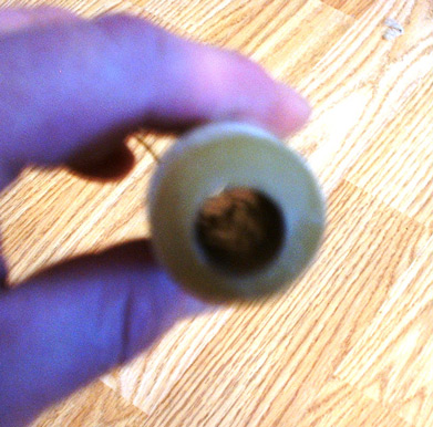 Next I went to work on the transition. As I noted before, FSI's transition was turned from hardwood and had a 0.69" diameter hole bored through the center from top to bottom. (See page 13 of the 1970 FSI catalog at Ninfinger for a detailed illustration of it). I needed to bore a similar hole through my balsa version, but I did not think that the balsa would hold together if I made it the same diameter as the original. I did the boring slowly, by hand, using a series of straight drill bits instead of hole boring bits. With a 3/16" drill bit held in a large pin vise, and working in from each end to keep the hole straight, I twisted out a small channel from end to end. Then, using a progression of larger bits, I enlarged the channel to 3/8" wide. I was worried, after that point, that drilling with anything larger would over-stress the balsa and cause the transition to break up. So I took the 3/8" bit and used it to gently scrape the insides of the channel, gradually widening it some more. This was the largest drill bit I had, but I wanted to get the hole to be large enough to fit in a length of ST-5, so I went out and bought a 1/2" drill bit, just for use in this series of cloning projects. After getting the channel to be large enough to allow the 1/2" bit through, I used the larger bit to even out the hole. Then I wrapped some fine grit sandpaper around a 1/4" dowel and used that to sand the inside of the channel smooth and get it to the final diameter needed to fit in the ST-5. Installing the tube served two purposes: to provide some internal support for the channel and to provide a lining to protect the balsa from getting charred by the motor's ejection charges. I used Aeropoxy 6209 Structural Epoxy to bond the 4.5" long tube into the channel, centering the transition between the two ends of the support tube.
Next, I tied a length of the Kevlar twine around the ST-8F end of the support tube just above the shoulder of the transition, and then applied more Aeropoxy in very heavy fillets between the transition and the end of the ST-5 at both ends. To keep the epoxy from dripping, I had to continuously rotate the assembly while keeping it horizontal until the fillets had firmed up enough, which ended up taking an hour and a half. I just kept it going while I watched TV, lightly touching the fillets every half hour or so to check for firmness. The process caused the fillets to assume the shape of little rounded cones of solid epoxy at each end. Then I slid the transition onto a length of 3/8" dowel and suspended it horizontally overnight to let the epoxy finish curing.
The next day, I test fit the transition into the lower body tube. The epoxy-filleted end of the ST-5 that extended below the wide end of the transition just reached inside the 0.5" of CR-9115 that extended above the motor mount. I slit and then glued in small sections of more ST-9 into the upper end of the CR-9115 to take up the internal space between the ID of the ring and the OD of the ST-5, so that when the transition was inserted into the lower tube, there would be a tightly sealed internal coupling between the motor mount and the transition channel that would prevent ejection particles and gases from reaching the inside wall of the lower body tube.
I coated the inside of the transition support tube with a thin layer of Devcon 30-min. epoxy. After that had set, I coated the inside of the inner coupling with 30 min. epoxy, and then bonded the transition into the lower body tube with more 30 min. epoxy.
 After the epoxy cured, I tied a #5 split ring to the the Kevlar twine that was bonded to the upper end of the transition at a distance above the end of the transition that would cause the ring would be just inside the upper end of the 8" length of ST-8F when the transition was inserted into it and then I trimmed off the excess Kevlar. I tied a 42" length of 1/4" wide flat elastic to the split ring, and then applied a drop of epoxy to each knot. I pushed the combination of Kevlar and elastic down through the transition and out the bottom end of the motor mount before bonding the upper tube to the end of the transition with 30 min. epoxy. After that had cured, I used a small diameter dowel to push the shock cord back up through the transition and out the top of the upper tube. The FSI instructions do not mention gluing the two tubes to the transition, but this step is shown in the cut-away illustration.
I made a wrap-around fin marking guide in VCP and used it to mark lines on the lower tube for the three fins and the launch lug. I extended the lines for the entire length of the tube, using a length of aluminum angle as a guide. I cut out one of the pictures of the Nova's fins that were included in the plans at YORP, and used it as a template to trace out 3 fins on some 1/16" aircraft plywood. The scan in the plans clearly shows the red edge of the fins, which was how FSI marked the root edge. Using a utility knife with a new blade and a metal straightedge, I had no difficulty cutting the fins out of the plywood. I smoothed the cut edges with some sandpaper but did not bother to round them. I tacked each fin onto the lower tube with gap-filling medium-cure CA, positioning them so that the bottom of the root edge was even with the bottom of the tube, and then gave each fin several light fillets with epoxy, allowing the adhesive to partially cure between applications. After it had fully cured, the fins were very strongly bonded to the tube.
FSI shipped the Nova kit with the tubes already marked for the fins and launch lug. Consequently the instructions did not provide specific information about where to place the launch lug on the rocket, other than saying to center it on the lower section between two fins. I trimmed a 1.75" long lug to 1.625" to match the dimension listed in the addendum, and glued it to the lower tube so that its lower end was 2.125" above the bottom end of the tube. The location looked about right when I compared it to the illustration in the plans.
I was concerned that the balsa nose cone had less mass than the hardwood cone that was used by FSI and I also wanted to be sure that my model would be stable if I flew it on Estes E9 motors, so I epoxied two 20mm diameter fender washers to the base of the nose cone, before bonding a screw eye to the shoulder with more epoxy. This noticeably increased the nose cone's weight, and now I am not sure that this step was actually necessary. I held off on tying the nose cone to the end of the shock cord, because I wanted to paint it separately from the rest of the rocket. Assembly of the Semroc CP-12BW chute kit went without a hitch, and I ended up with a very nice-looking blue and white 12 inch diameter plastic parachute. I finished it by tying a #3 brass snap swivel to the bottom of the shroud lines.
Finishing: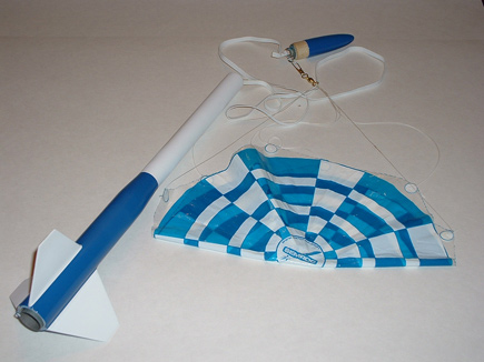 I applied 6 coats of Future floor finish to the balsa nose cone by immersing it into a jar filled with the finish up to the shoulder line for 30 seconds at a time, then withdrawing it and letting the excess drip off, occasionally giving it a shake, and then hanging the cone up by its screw eye to dry for a couple of days between coatings. I gave the nose cone a light sanding after every second coating had dried. Then I brushed on 3 coatings of Pine-Pro, a water-based balsa filler and sealer to the nose cone, the transition section, and the plywood fins, giving each surface a light wet sanding with 400 grit sandpaper between coats. I then gave the entire rocket and nose cone a light coating of Krylon white primer. After the paint had dried overnight, I wet sanded the nose cone again and set it aside. I gave the rest of the rocket a good sanding with 240 grit sandpaper until most of the primer was gone, tack-ragged it, and then applied thinned Fill 'N Finish to the shallow spirals in the tubes. Once they were dry, I sanded the tubes again, and then gave the entire rocket and the nose cone three light coats of Duplicolor High-Build Primer. After the primer dried, I gave everything another wet-sanding and let it dry overnight. Next I sprayed on another coat of Krylon white primer, lightly dry-sanded it, and then followed it up with two coats of Krylon Gloss White.
I wanted to give the Nova the same paint pattern that is depicted in the drawing of it in the 1971 FSI catalog, so after allowing the paint to dry for a couple of days, I masked off the fins and the upper body tube starting just above the transition. I sprayed one light coat of Krylon Gloss True Blue onto the exposed areas, and, separately, onto the nose cone. I removed the masks after about 6 hours, and then allowed everything to dry for another couple of days. Finally, I tied the end of the shock cord to the screw eye in the nose cone, which completed the construction.
There is a scan of a decal in the YORP plans for the Nova, but it is for a later color scheme, so I did not use it to make decals for my version. At some point I will try to recreate the decal set shown in the 1971 catalog drawing. I was quite pleased with the way that this color scheme turned out.
Flight:
I built my Nova two years ago this month, but I held off on flying it until I had it painted, which I finally did this year. (I know - I'm really courting bad luck there.) And then a variety of factors conspired to keep me from flying it, or much of anything else either this year. According to RockSim 8, though, it should get almost 700 feet on an Estes C6, and over 1500 feet on a D12. (It would roar to over 4300 feet on Aerotech's new F35 reload for the 24/60 case. I doubt that I would want to risk losing the casing for such a flight, but it's interesting to contemplate, though.) My sims show that the Nova will fly best on these two BP motors (at least it won't totally shred its chute), but I may try others, too. The mount can accommodate 3.75" long motors; to fit in the shorter 2.75" long black powder motors and the RMS 24/40 case, I will use a Semroc HTC-8F coupler as a spacer. Using a coupler for ST-9 or BT-50 tubing as a spacer is usually recommended in this situation, but I have always had a great deal of difficulty getting those spacers back out of the mount, because they were designed to fit snugly into the tube to begin with. ST-8F has a slightly smaller ID, so that coupler slips into a 24mm motor tube and comes back out easily, yet it has a large enough diameter to do the job. The 8F coupler is also the right length (1"). A spent Estes E9 motor, cleaned of its nozzle and burnt propellant residue, will make a dandy adapter for the 18mm C6 in the Nova's mount. In any event, this rocket looks like it will be a real screamer. I will add flight logs as I get them.
Recovery:
As I mentioned earlier, I assembled a Semroc 12-inch plastic parachute for this rocket. For its initial flights, though, I may substitute an equivalent sized nylon chute, either regular or thin-mil or possibly even use a streamer. FSI instructed the flier to place a ball of flameproof wadding in the bottom end of the upper tube, just above the transition. This arrangement, combined with the fact that the ejection charge will be coming through a half-inch diameter channel through the transition, may work particularly well to protect the parachute from burns during ejection. In the FSI instructions, the shock cord was anchored to the inside wall of the upper tube, just below the nose cone, using a mount that appeared to be very similar to the type used by Centuri. I chose the more modern method of tying the shock cord to a Kevlar leash that is anchored to the upper shoulder of the transition inside the bottom end of the upper tube. This allows the cord to extend straight up and out the top of the tube with the rest of the recovery system at deployment, without presenting any structures along the inner wall that could snag the chute as it is being deployed. In a personal little touch, or perhaps it's more of a quirk, I finished off the upper end of the Kevlar leash with a small split ring, onto which I tied the shock cord. This was purely optional, though. (I include it in all of my builds.)
Summary:
The MRK-III Nova is very typical of FSI's early designs. Long and sleek, with an elliptical hardwood nose cone, a hardwood blow-through transition and thin plywood fins, it was designed to be a durable rocket that was capable of reaching impressive altitudes for a model of its size. Reproductions of all of the key components (except for plywood for the fins) were readily available from Semroc, and the quality of the parts was uniformly excellent. There are easier FSI clones to build, but I wanted to immediately tackle the biggest challenge of this build - creating the channel through the transition. This was quicker and easier to accomplish than I expected, but still, this was a solid Skill Level 3 build, possibly even higher. Along with creating the channel, I had to cut the fins from a hard material, trim one of the body tubes to size, reinforce the channel for the ejection charge and create my own shock cord anchor/leash. The instructions in the artistically-drawn plans are actually pretty good, but they require careful reading, and they leave out some key measurements and one obvious step. I had to study them carefully, and then develop my own construction strategy. The color scheme depicted on the front page of the 1971 plans is, like the rest of the Nova, simple yet elegant, and reproducing it gave me a handsome-looking rocket; unfortunately, no one currently makes reproduction decals for that specific decor, and there are no published scans of them, either. The Nova can fly on 18mm motors as small as a B6-6, as well as on 24mm black powder and composite motors with long delays, but you might want to hold off putting it up on the larger motors until you have an appropriately large field and some spotters, because this design will quickly attain some serious altitude.
Other:
I will be uploading my RockSim 8 file to EMRR to accompany this review. I have adjusted the design with mass objects here and there to match my model's overall weight and CG location. Feel free to try out different motor/delay combinations with it to get something that doesn't have a chute-shredding deployment speed. The three motors that seemed to work the best for me in simulations were the Estes C6-7 and D12-7, and the Aerotech F35-11 reload for the new RMS 24/60 case.
#Related Reviews
- Modification Cherokee D (Cloned from a CC Express Kit) By Ronald West
My clone of the very popular Este's K-47 Cherokee-D that was available from 1971 until 1983. Its 3FNC design and D power really packs a wollop off the launch pad. My review is very similar to the other Cherokee-D with the exception I used a E engine hook to allow either a E or with a spacer, ...
- Modification Meanie w/Quick Change Motor Mount By Nick Esselman
I had the idea one day to make a switchable motor mount so that I could fly a rocket on various motor sizes and configurations. I searched the web and found I wasn't the first to have that idea (no surprise there). Then I connected with Mark over at True Modeler Rocket Kits . He is selling his ...
- Modification More G-Force DD By Frank Hermes
See prior article describing what basically was a MMT modification to the G-Force kit --I kept that modified booster section onl y, and added scratch components to turn it into a dual-deployment version. I added a fully redundant dual-deployment mid-section e-bay for the flight computers and the ...
- Modification Pipsnitch By Chan Stevens
What do you get when you rummage through the build pile 2 nights before a 2009 challenge deadline trying to come up with stage bash ideas? The answer is the decidedly low-labour Pipsnitch, a saucer-based screamer. It made use of one of the many clearance-sale Snitch's I'd picked up at about $3 ...
Related Products
- FSI Nova MRK-III/1003
 |
 |
Flights
|
|
|
|
woody (April 28, 2011)
Hey I looking for a rocket like that!!! Thanks. Also I think your finshining techneques are better than mine. Future floor finshish hummm? Thinking and thinking and thinking and thanks.lol Clifford w Crawford.