| Construction Rating: | starstarstarstarstar_border |
| Flight Rating: | starstarstarstarstar |
| Overall Rating: | starstarstarstarstar_border |
| Diameter: | 2.60 inches |
| Manufacturer: | The Launch Pad  |
| Style: | Scale |
 Brief:
The Launch Pad's Type-30 Artillery Rocket is a good introductory kit to mid-power rocketry. It's fairly easy to build and it flies great!
Introduction:
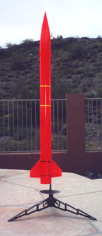
After launching model rockets with my eight year old daughter for some time we learned that the smaller the rocket the harder it is to find after each flight. Our most successful rocket was Big Bertha, which was easy to find and convinced me that bigger is the way to go. So I decided that it was time to move up to the next size, a 24mm D-engine size kit. I looked at Estes' D engine kits like the Super Big Bertha and the Big Daddy, and then began searching the Internet for other possibilities. The Launch Pad's kits caught my eye because they had many models that flew on 24mm engines and they also claimed to be launchable from the standard Estes pad that I already owned. The Launch Pad specializes in scale models of military missiles, and most of them have lots of fins, which was more complicated than I wanted. At the bottom of their list was the Type-30, which was pretty close to a basic nose cone, body tube and four fins rocket. At nearly 41" long and 2.6" in diameter this seemed to be the biggest and easiest 24mm rocket kit around, so I decided to go for it.
Construction:
I ordered the kit from Performance Hobbies and it arrived in about a week packed in peanuts. Ken at Performance Hobbies was very helpful and took time to answer a lot of my questions about construction and flight of a kit larger than I was used to. I definitely plan to order from them again.
Initial Condition of Kit - The kit was in a clear plastic bag and looked to me pretty much like an overgrown Estes kit: Cardboard body tubes, injection-molded plastic nose cone, balsa fins. The kit was complete and all parts arrived in good condition. The instructions were on two double-sided 8.5"x11" sheets, and were fairly easy to follow. There are a couple of things that I would do differently if I were to do it again though.
Engine Mount - The engine mount uses a steel clip to hold the engine at both ends. This is OK for the black powder D engines, but I picked up a 24mm Aerotech RMS motor and the clip seems a little light. So far it hasn't actually been a problem, but next time I would put in some type of engine block at the forward end of the motor mount and a better motor retention system in. But these would both drive the weight and price of the kit up, so I think that TLP is doing the right thing by providing the clip. The kit as sold is complete and flyable.
Paper Nose Cone Extension - The paper nose cone was a hassle due to my inexperience -- I made a few painful mistakes, but I learned from them. Following the instructions, I cut out the pre-printed heavy paper cone and steamed and rolled and steamed and rolled and glued and eventually had a decent looking sharp-pointed paper nose cone extension. Then, per the instructions, I put CA adhesive around the inside base of the cone and set it on the plastic nose cone (mistake #1). The instructions do say to make sure to get it positioned straight very quickly or the CA will grab, and they sure were right about that. It grabbed, and I ended up with a gap on one side between the paper cone and the plastic nose cone. Of course I didn't notice this until I had already coated the paper cone with CA adhesive, and getting it off was not fun. Construction paper, when saturated with CA adhesive, becomes very stiff and hard to cut. To get the paper cone off I had to use my razor knife to literally whittle the cone down to the plastic nose cone. I was taking off tiny crumb-sized bits of paper-reinforced solid CA with each cut. After a lot of effort I got most of the paper and CA off and was left with a rough surface on the top of the nose cone that I sanded down with medium grit sandpaper. Luckily I had copied the nose extension cone pattern before cutting it out, so I could make a new one. This time I didn't try putting CA on the paper cone and then positioning it, but instead I held it in position and then wicked the thin CA in between the paper and the cone. Then I proceeded to paint the paper with CA and I thought I was back on track again. Unfortunately the paper I selected wasn't as absorbent as the original that came with the kit, and consequently did not absorb the CA as well and ended up feeling a little soft and wimpy (mistake #2). So once again I spent an evening whittling it all off and started over again using construction paper this time. The construction paper did absorb the CA very well and became good and solid. Whew.
Nose Cone Finishing - The instructions suggest a few coats of sanding sealer and sanding to smooth the transition from the plastic nose cone to the paper extension. I painted the whole thing with thinned Fill n' Finish and sanded it lightly to fill in the step up where the paper starts. It worked and the nose cone looks good.
Fin Strengthening with CA - Did I mention that this was the first time that I had used CA in a rocket kit? My next misadventure was in coating the balsa fins with CA. The instructions don't say anything about this, but the FAQ on The Launch Pad web site recommends painting the balsa fins with thin CA to give them strength. I decided to do this before I glued the fins onto the body tube so that I could sand them easier. A good idea, but a little tricky. The hard part is putting the fin down after it is fully coated with CA. They love to stick to your fingers and damn near anything else that gets too close. I set the fins on waxed paper to dry and amazingly enough they didn't stick to that. The actual problem was that two of the fins ended up a little warped. Had I glued the fins to the body tube before coating them with CA they might not have warped as much and handling them by the body tube while the CA was still wet would have been much easier. I had considered this, but decided that it would be easier to sand the fins before gluing them to the body, and if they had warped after being glued to the body it would be difficult to repair or replace them. Disappointed with my warped fins, I ran out to the hobby shop and bought some more balsa and cut out another set of fins. Three of these warped as well. I decided to try to straighten the fins out, so I heated one up by ironing it on both sides in a piece of folded paper with an iron set on low, and then quickly pressed it flat while it cooled. This worked great and it was easy too! In the future I'll just plan on ironing the fins after coating them with CA instead of stressing about them warping.
After I got the fins strengthened and straightened I beveled the edges to make them more aerodynamic. I put a piece of medium sandpaper on the table and held the edge of the fin at an angle to get the bevel. Unfortunately the balsa fins are pretty soft and the results are not very even. Holding the fins by hand and sanding one side at a time just doesn't work very well. The amount of material removed varied along the length of each edge of the fins as well as from one side of the fin to the other. I got it as close as I could, and once painted it isn't noticeable unless you're looking for it. Next time I plan to build a tool to make this easier.
Assembly of Body Tube - The body tube is in two pieces, each about 16 inches long, which go together using a coupler to make one big long tube. The instructions actually say to join the two body tube segments together prior to installing the engine mount assembly and the parachute compartment disk, but this seemed like a bad idea. Had the tubes been connected it would have been impossible to put an epoxy fillet to the inside of the body tube at the forward end of the engine mount or on the aft side of the parachute ring.
This was also my first time using epoxy, but that was much more forgiving than CA and didn't lead to any problems. In general I used 5 minute epoxy to put things together and 30 minute epoxy for fillets. Attaching the motor mount was challenging because the forward centering ring is nearly 12" from the end of the aft body tube, which made it tough to get the epoxy down to it. Using a thin bamboo skewer I eventually managed to make a reasonable fillet between the centering ring and the tube without getting too much glue up and down the inside of the tube.
Tube Marking and Launch Guides - The rocket also has four "launch guides" which are 1" long pieces of 1/8" by 1/16" balsa strip that get glued on just behind the nose cone in line with the fins. These probably have some function in the real rocket, but are purely decorative in the model. I overlooked the little balsa strip and ended up using the 3/32" fin stock which worked out just fine. The ends of the strips are supposed to be rounded and it took a very light touch with the sandpaper to get them consistent -- it would have been even trickier with the supplied 1/16" balsa. I bought a 3' piece of 3/4" x 3/4" aluminum angle stock for $2.00 at the hardware store, and used it as a straight edge to mark the body tube for the fins and launch guides. That worked out well and everything ended up well aligned.
Launch Lug Installation - The kit comes with a launch lug for a 3/16" rod, but the instructions don't say where to mount it. I know that The Launch Pad FAQ says that you shouldn't attempt his kits unless you have enough experience to know where the launch lug should go, but a suggested location would have been nice. I ended up putting it just forward of the fins. This is aft of the CG, but I wanted it to have a long run up my 3' launch rod. If I put it farther forward then it would come off the end of the launch rod sooner, and I didn't want that. The lug is long enough that it will hold the rocket straight regardless of where it is mounted, so location isn't critical. If I were to build this kit again I would cut the lug in half and put one piece at the current location near the fins and another closer to the rocket's c.g.
Fin Fillets - I put in generous fillets of 30 minute epoxy at the root edge of the fins, launch guides and launch lugs. I set the rocket on a table with the fins hanging over the edge. I set a couple of books on either side of the body tube to keep it from rolling. With the fins at 45 degrees from vertical and horizontal I did the fillets on the upper side of two fins and two launch guides at a time. The 30 minute epoxy was thin enough to form a very nice smooth fillet. I did all the fin fillets with four rotations of the body. Two more rotations were required for the fillets on the launch lug.
Filling Spiral Groove - I tried Fill n' Finish to fill in the spiral groove in the body tube, but it didn't work out very well. I thinned the FnF and painted it over the groove. When I tried sanding it I discovered that FnF is harder than the cardboard body tube, and I was roughing up the tube and the FnF wasn't getting any smoother. I then got a damp rag and washed the FnF off the body tube. Two or three thin coats of white primer helped fill in the groove, but it is still visible if you look closely. I need to figure out a better way to fill the spiral groove in the future.
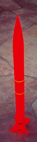
 Painting - The scale instructions for finishing say to use dark green or olive drab, but I care more about finding the rocket than being true to scale, so I used a day-glow orange paint. Just to be sure that it is visible I coated the bright orange with clear gloss. It's bright. I did add the black and yellow bands at the correct locations per the instructions with striping tape. The bright orange really changes the look, but it's really easy to see.
Recovery System - The recovery system consists of an 18" mylar hexagon. The shock cord is about 3' long 1/4" flat elastic. The shock cord mount is a simple paper mount to the inside of the body tube. I put a generous bead of epoxy around the edges of the paper mount to ensure that it won't pull off. The chute attaches to the shock cord with a snap swivel. The nose cone is attached to the shock cord by a 10" piece of shroud thread. The kit requires wadding, but I purchased a reusable chute protector which is a round pad of Nomex and other fireproof material that ties to the shock cord with a Kevlar thread. It makes for an easy preparation and I don't need to worry about wadding.
Construction Rating: 4 out of 5
I rate the construction and finishing at 4 out of 5. The problems I had were primarily due to inexperience with CA adhesive and really weren't the manufacturer's fault. I would suggest that they add notes to the instructions to recommend coating the fins with CA as their web site FAQ does. This is a really good idea -- I think the balsa fins would be too weak for the E and F motors if they weren't soaked with CA or otherwise reinforced. The buyer shouldn't have to do a research project to get the complete instructions. Also the instructions could recommend a location for the launch lug. These are really minor issues and didn't really pose a serious problem for me even though I hadn't built a kit this size before.
 Flight:
The instructions recommend the following engines: Estes D12-5 for first flight, and Estes D12-7, Aerotech E15-7W or E30-7. The package (but not the instructions) recommends the Aerotech RMS F24-7 as well. For my first flight I decided to follow the recommendation and use a D12-5 motor. The first thing I discovered is that the rocket is taller than my 36" launch rod (well duh, but it hadn't really hit me until I actually put it on my little Estes Porta-Pad). The tip of the rod comes up to the aft end of the nose cone. Oh well, the web site said that it was launchable on a standard Estes pad, so what the heck. The first launch was at the January launch of the Superstition Spacemodeling Society in Phoenix, AZ. There was some noticeable friction between the rod and the launch lug, and I was more than a little worried that it wouldn't launch cleanly. My worries were totally unfounded because it flew straight and true. It wasn't a particularly high flight (wRASP predicts 330'), but it was straight and the chute deployed pretty much right at apogee. There was very little wind and it came down very close to the pad and I was able to catch it before the it hit the ground (I guess this is frowned on, but the rocket only weighs a half pound and I really wanted to keep the paint job pristine). The 18" hexagonal mylar chute lets it come down fairly fast, but slow enough to survive.
For the second flight I decided to try my RMS motor for the first time. I bought E18-4 reloads, but later I realized that the recommended delay is 7 seconds not 4, and that the RMS E18 isn't even one of the recommended motors. After stressing over this for a day I convinced myself that it would be fine. At the February SSS launch I flew my Type-30 on the E18-4 and it was another perfectly vertical flight without any wobble with ejection very close to apogee. wRASP predicted over 900', but once again it came down close to the pad. This time it hit the ground and the aft end of the body tube got dinged a little where it hit.
I look forward to flying this rocket on the F24.
Flight Rating: 4.95 out of 5
It would have been a 5 for two perfect flights in two attempts except for the minor ding on the body from the second landing. The chute size could be slightly larger for a softer landing. Even with the largest recommended engine this isn't a high altitude flyer, so a larger chute wouldn't be such a bad thing.
Overall Rating: 4.75 out of 5
I have to give this rocket a 4.75 out of 5 rating. It's such a great flyer, and that makes up for the minor hassles during construction. I highly recommend this kit for anyone looking for a 24mm motor rocket.
Other Reviews
- The Launch Pad Type 30 By Greg Deeter
This is a single stage rocket, nice sized, over 3 feet tall. Skill level (2), being the most simple kit offered by The Launch Pad. It comes in a large retail type (Estes type) plastic bag with a peg hole punched header card and a full color cardboard insert which looks very nice. I purchased this kit and two other Launch Pad kits (the two others being the HARM and ALARM) at the same ...
- The Launch Pad Type 30 By Darren Collins
( Contributed - by Darren Collins) Brief: One of the larger scale kits by The Launch Pad. Listed as a skill level 2, but I think this is the easiest level this company makes. Construction: Packaging was good. No damage. All parts fit okay. I coated the balsa fins with thin C.A. glue as suggested after cutting them out. This caused them to warp a little, but I was able to hold them ...
 |
 |
Flights
|
|
M.A. (June 14, 2009)
|
|
A.J. (December 7, 2002)