Level 1 Cert - Madcow Rocketry - Patriot
By Skyviper Aerospace
2013-02-16
This build of the Madcow Patriot 4" version is my Level 1 certification build. I'm starting this build in the Winter months with the hope to be completed and ready to fly in the early spring.
Unpacking the box
2013-02-17
I opened the box and carefully laid out the contents to be sure nothing was missing or damaged. Everything seemed to be present and in good condition.
This is what you get in the kit. I ordered my kit from Apogee Components and it included the nylon chute. The kit has a 38mm motor mount. (The motor retainer seen on the right side of the picture is NOT included. I purchased it separately.)
The Motor Mount
2013-02-18
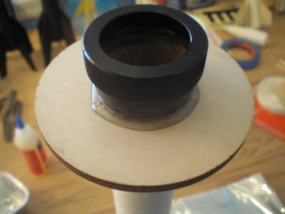
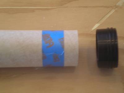
The first step in building the motor mount is attaching the motor retention system. I choose to use an Aero Pack Quick-Change Motor Retainer. This allows easy installation and removal of the motor.

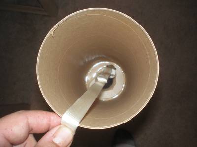
In this image I have test fitted the motor retainer and taped off the area so the JB Weld I use to attach it has a neat edge.
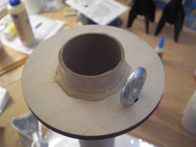
Here is the motor retainer attached with JB Weld. I removed the tape before it set up so I would have a neat line.
Here I have test fitted the motor mount centering rings. I have the lower ring almost against the motor retainer so the motor is as far into the rocket as possible.
In these two pictures I have used Epoxy to secure the two centering rings in place.
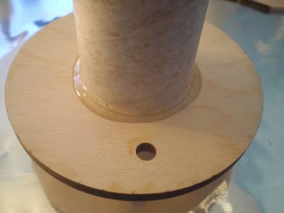
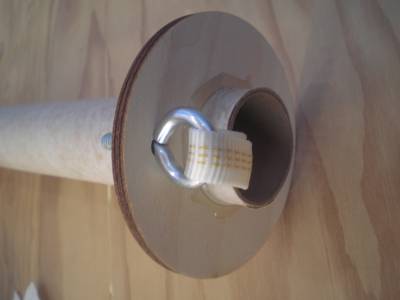
I added more Epoxy to the opposite side of the foward centering ring and installed the eyebolt for the shock cord. (I didn't add Epoxy to the backside of the aft centering ring so it wouldn't interfere with the root of the fins when they are installed later.
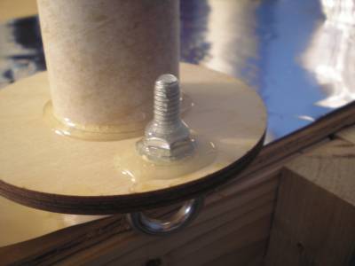
In this picture I have applied Epoxy to the threads and nut securing the eyebolt.
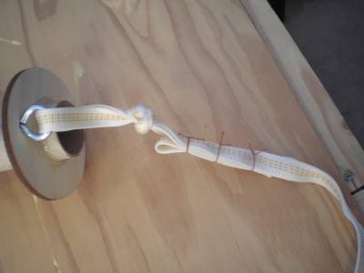
I next attached the shock cord to the motor mount with a simple over under knot and secured the tail end with Kevlar thread.
Finally I stuffed the 12 feet of shock cord into the motor mount in preparation for inserting the motor mount into the body tube.
Installing the Motor Mount and Fins
2013-02-23

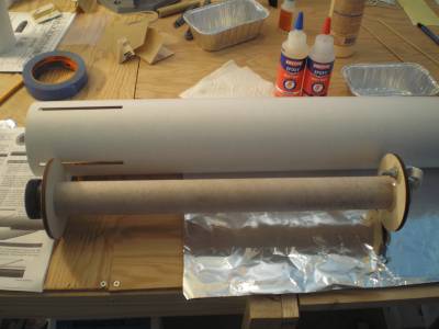
Here I have laid out the the motor mount against the body tube in preparation for installing it.
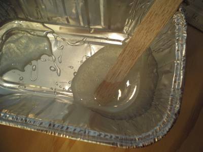
I mixed the epoxy and spread a generious amount of it on the inside of the aft end of the body tube above the fin slots.
After carefully sliding the motor mount into the body tube until the lower centering ring was against a fin held in place to position the motor mount, I pulled the shock cord out of the motor mount and held it away from the drying epoxy.


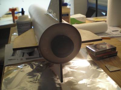
After the epoxy set on the foward centering ring, I turned the body over and spread epoxy on the aft centering ring to complete securing the motor mount. Notice I have the fins inserted throught the fin slots to ensure that the motor mount is positioned correctly and not interfering with the fin instalation.

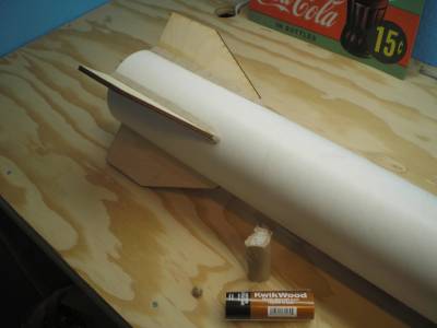
I next applied epoxy to the fin roots and inserted them into the body.

Here I have all four fins installed and the epoxy is setting. Next I will have to make fin fillets out of epoxy.
Parts Arrived
2013-02-26
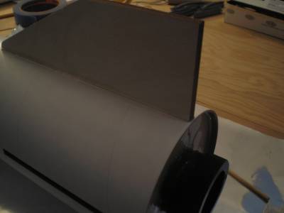
This is just a quick post to show the Electronics Bay and the nose bulkhead I ordered.

Building the Electronics Bay - Avionics Sled
2013-03-01
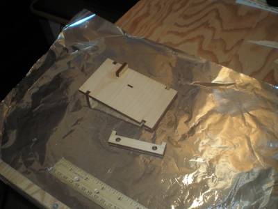
I started building the E-bay last night.
The first thing I did was to attatch the 1 inch section of body tube I cut from the foward section of body tube to the middle of the E-bay. I used regular carpenters glue to do this.


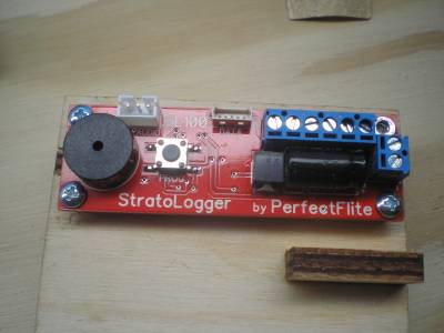
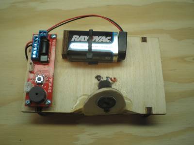
Next I set aside the E-bay tube and started work on the avionics sled. The first peice I attached was the battery holder. I used carpenters glue for all work on the sled.
Finally I attached the two sled holders to the bottom of the sled.
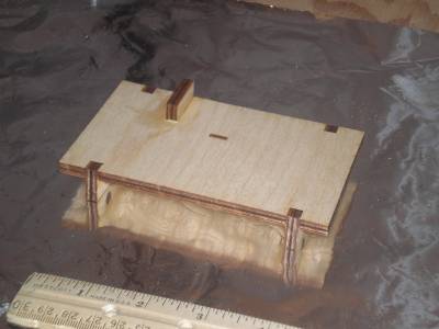
I will assemble the E-bay tube next.

The rest of the build!
2013-04-28
Considering I have already flown this rocket for my L1 certification and was successful, I figure I should finish documenting the build before I send it up for my L2 cert. next weekend.


For the fillets I used wood epoxy and then topped it with 5 min. epoxy for a smooth finish.

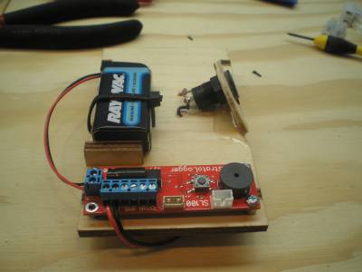
This is the e-bay sled layout and assembly.
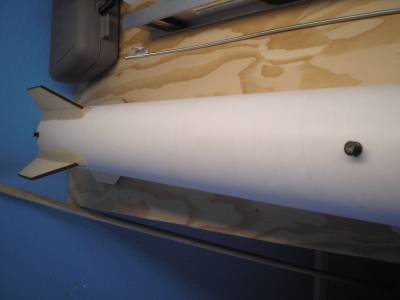
Here I have installed the rail buttons.

This image shows the construction of the ejection charge holders. The mounting hole is on the bottom, the hole that is drilled on an angle is for the electric match wires.
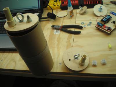
Here I have installed the ejection charge holders on the e-bay bulkheads.
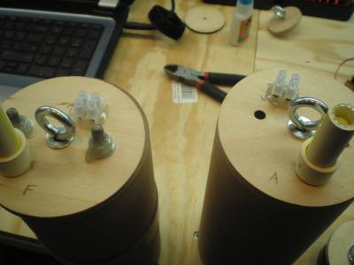
This image shows the power terminals for the electric matches installed on the e-bay bulkheads.
Here the disconnect plug on the aft end of the e-bay has been installed.

I drilled small holes and used a thread tap to make threaded holes for the sheer pins in the nose.
This is a close up of the nylon sheer pins used in the nose cone/upper body connection.
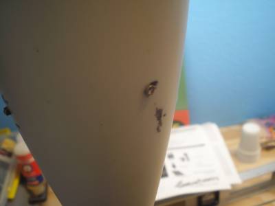
I added weight to the nose to move the CG foward. After pouring lead shot and epoxy into the nose, I drilled four holes and inserted straight nails through the nose cone. I then added more epoxy. The nail heads will be ground down smooth with the surface of the nose cone.
I epoxyed a bulkhead with eye ring and shockcord attached into the nose cone and secured it with screws through the nose cone also.
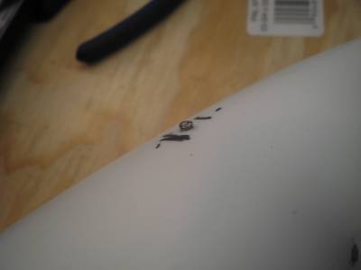
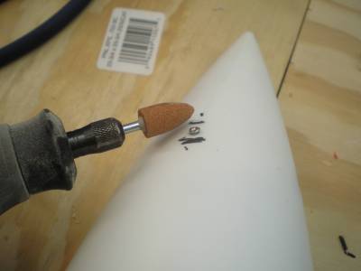
The nails and screws were then ground down with a grinding wheel on a Dremel tool.
At this point I tested the ejection charges with all the parachutes and Nomex packed in the rocket and painted it. I will post a separate build article about how I made my ejection charges at a later time. They were easy to make and I found the idea on TRF.
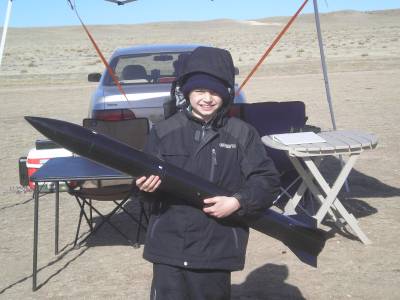
Here is a picture on my son holding the rocket before we launched it for my L1 cert.
 |
 |