Red Spike - 2010 Design This Spaceship Contest Entry
By Dale Marshall
2011-05-03
 When looking over the design possibilities for this contest, I was intrigued by all of them, but the only one I felt comfortable building at my current skill level was the red & white one with the huge nosecone. My first attempt at this build (Mini Red Spike) failed miserably when the rocket arced off of the pad and into the ground where it smashed itself to bits before the ejection charge finished the job.

Parts List
2011-05-04
The parts list for this rocket is quite extensive.
1 - PNC-66A
3 - NC-5 (Conical shape from the Estes nosecone pack)
1 - BT-80 (4 5/8”)
1 - BT-60 (9”)
3 - BT-20 (4”)
3 - BT-5 (5 ½”)
1 - 24mm EngineMountKit
1 - Engine Hook
8 - BT-6080 Centering Ring
6 - BT-0520 Centering Ring
6 - Balsa fins
1 – 3/16” Launch Lug (2” long)
1 - 18” Parachute
1 – Sheet of bubble wrap (you’ll see…)

The Build
2011-05-04
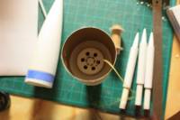
After building the Red Spike in RockSim, I took the original images provided on the website and sized them to fit the BT-80 nosecone. I printed out several copies to use as templates and guides. The first thing in the build was to cut the base of the nosecone off leaving a 1” shoulder. Then, I cut the BT-80 and BT-60 to size and build the engine mount. Next, I installed the six centering rings evenly spaced on the last 4” of the BT-60 and glued the BT-80 over them (see the RockSim file). I then constructed and installed the BT-60 baffle in the top of the main body tube (should have done that first!) and the engine mount into the other end.

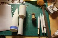
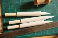
Next I worked on the wing pods. I cut the BT-5s and BT-20s to size and glued the nosecones into the BT-5s. I installed the centering rings around the BT-5s and inserted them into the BT-20s leaving 4” hanging out one end, giving the other end a sort of “ramjet” look. In hindsight, I should have planned the location of the centering rings a little better as you will see later.
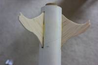
Finally it was time to work on the fins. In the image, the fins are strangely shaped and the rear fins are very thin at the top. I printed a copy of the image full-size, and cut out the fin parts and used them as a template and cut the fins out of 1/8” balsa. I wasn’t comfortable with just gluing the fins to the body tubes and pods, so added extra length to the top and bottom to make them through-the-wall. At least the rear fins are, and also where they connect into the pods. I had to notch the upper parts of the fins because of where I placed the centering rings in the pods. I don’t believe it will impact stability, but those pods are just asking to break off on landing anyway. I carefully measured for the fin slots and cut them in the main body tube and the pods. Turns out the rear fins are longer than the body tube, too, so I had to cut a notch for the interior centering ring as well! A longer engine mount tube would have avoided this problem.
After installing the rear fins, I realized I had forgotten to install the pair of centering rings to support the transitions! Oops. So I cut the rings in half and glued them onto the body tube right up next to the lower fins (offset to the cut edges weren’t lined up).
Next I re-measured the space available and used the Template Wizard (from EMRR) to print out the two transitions (one 3” long and the other ¾” long). I cut them out and dry-fit them to ensure they were the right size. With the rear fins installed I had another problem – I couldn’t properly install the rear transition! I traced the two transition patterns onto poster board. The rear transition was broken up into three oversized pieces so there would be some overlap for strength. The front transition went on smoothly and then the rear transition pieces (slotted to fit over the fins).
To complete the main body I glued the front fins (through-the-wall into the pod but not into the main body tube) and pods on and lined everything up. I chose to place a strip of 1/8” balsa under the launch lug to offset it from the rear transition just in case.
I glued a piece of shock cord into the nosecone using a standard tri-fold mount and tied that to the Kevlar cord in the baffle. Finally, I attached the 18” parachute to the shock cord.
Finishing
2011-05-04
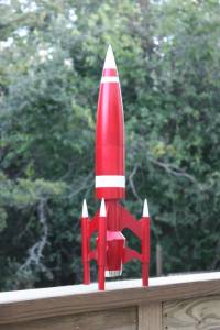
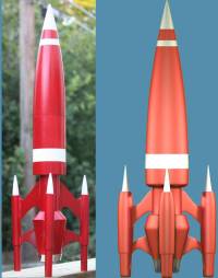
To finish the Red Spike, I filled all of the seams and made fillets out of wood filler and smoothed and sanded it all. I sprayed a coat of white primer and sanded it down. I masked off the white areas and sprayed on Testor’s “Revving Red” model car paint. I really like the look of this glittery paint! As a final touch I added some Monokote Chrome trim to the tail to simulate the engine nozzle as on the original image.
Here is a comparison to the original image the Red Spike was built from.
Flight!
2011-05-04
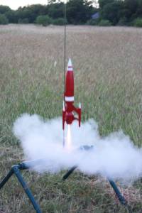
This rocket is sized for 24mm engines and simmed to fly to 230’ on a C-11 engine and to 655’ on a D-12. I decided to try out the stability on the C-11 first. On launch, the Red Spike arced over a little (maybe a little nose-heavy) but stayed stable and the parachute ejected as planned. On the second flight, also on a C-11, it again arced over but this time the parachute didn’t deploy because it got stuck in the nosecone. Fortunately I was flying in a field of tall grass so the Spike landed softly and nothing broke. I added a wad of bubble wrap in the nose to keep the parachute from getting stuck up there. The next day I took the Red Spike to a nearby soccer/football field and launched again. This time I had a video camera with me. The third launch was a repeat of the first one, on a C-11, and this time the parachute came out as planned and landed it fairly softly. The fourth launch was on a D12-3 and it soared! The parachute deployed and the whole thing came down fine. It did crack a couple of fins on landing but that was expected. See the video for details.
Final tally – Four successful launches on two different engines, three successful deployments, and two cracked fins. Already repaired and with a larger parachute ready to fly again!

Overall Impressions
2011-05-04
This was a very fun rocket to build, and it wasn't too hard despite the complex curves and tight fit of some of the parts. The rear paper transition was the hard part, making sure it fit properly around the fins. But overall it was a great experience. This one sure draws eyes on the flight line, and its performance off the pad is great!
I'd give it a skill level of 2, maybe 3. I've attached the RockSim file so others can build it. I wouldn't count on the file for the fins, though, since they were roughly drawn there. Take a copy of the original image, size it to the nosecone, and print that out for the fin templates. Remember to add a bit for TTW mounting!
 |
 |