| Manufacturer: | Polecat Aerospace  |
Note: This is a slightly condensed version of all the information that Mike has produced for his Level 3 project. Visit his site to read the additional information and enjoy additional pictures (and video).
Brief:
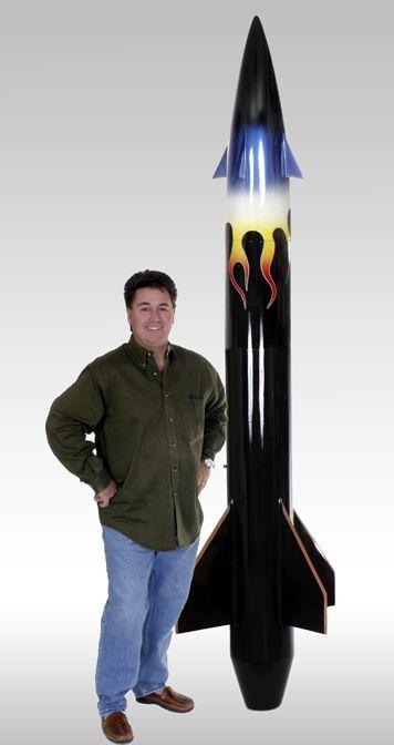
The Polecat (formerly Skunk Works) 10" Bull Pup utilized for my Level 3 Certification.
 Parts List
(Kit - 10" Polecat Bull Pup fiber glassed Airframe)
List of Materials:
(1) Slotted nosecone
(1) 10” boat tail
(1) Body tube - slotted
(1) 18” body tube
(1) 11” coupler
(4) Main fins
(4) guide fins (nose)
(1) Nose bulkhead
(1) Upper electronics bay bulkhead
(1) Lower electronics bay bulkhead
(1) upper centering ring drilled
(1) Lower centering ring
(1) boat tail centering ring
(1) 98mm motor tube
(2) electronics bay slides
(1) Electronics mount
(4) U-bolts with plates
(24) 1/4”-20 nuts
(20) 1/4”-20 washers
(4) 12” long 1/4-20 threaded rods
(1) 20’ shock cord (apogee)
(1) 10’ shock cord (main)
Through the wall fin mounting for main and guide fins
Fiberglass molded nose cone, slotted
Fiberglass molded boat tail
Fiberglass and slotted body tube
Baltic Birch fins and centering rings
Fiberglass electronics bay
98mm motor mount
Tubular nylon shock cords
Steel u-bolt Shock cord mounting hardware
Dual deployment
Fully redundant ejection charges
Nomex®
blanket for main and drogue parachute protection
Nomex®
shock cord protectors
17' Domed Mil-Spec Cargo Main Parachute
Fully redundant backup recovery charges
Multi redundant power sources for electronics
External key switches for recovery system arming
West Systems epoxy adhesives used throughout
AeroPac Motor Retention system
Construction Details and
Photographs
After a deep breath the construction begins...
Step 1 - Electronics bay assembly - 11/29/2003
 Forward bulkhead is assembled using 1/4 inch
all thread (9.25" long) and is attached to forward bulkhead with 1/4 nut
and washer on each side. At this time two charge holders constructed of heavy
polycarbonate are attached to both the forward bulkhead and the electronics bay
cover (aft) with 3/16th nuts and washers.
Forward bulkhead is assembled using 1/4 inch
all thread (9.25" long) and is attached to forward bulkhead with 1/4 nut
and washer on each side. At this time two charge holders constructed of heavy
polycarbonate are attached to both the forward bulkhead and the electronics bay
cover (aft) with 3/16th nuts and washers.
The attachment point for the fore parachute harness is also attached at this time with 1/4 inch steel u-bolts with a washer and 1/4 nut external and a steel plate spanning the u-bolt and 1/4 nuts internal All connections tightened.
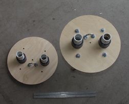
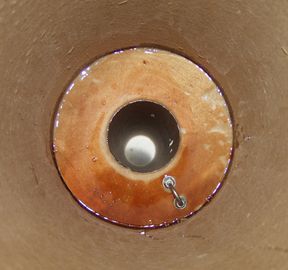
Step 2 - Upper Centering Ring - 11/30/2003
The attachment point for the drogue parachute(s) harness is attached at this time with 1/4 inch steel u-bolts with a washer and 1/4 nut external and a steel plate spanning the u-bolt and 1/4 nuts internal.
After sanding to roughen up the end of the 4" motor mount tube the centering ring above is attached to the motor mount tube with a liberal application of medium fast Epoxy. Once dry, a second application of Epoxy is applied to the underside of the centering ring where it meets the motor tube. The nuts attaching the harness attachment point (u-bolt) are also epoxied.
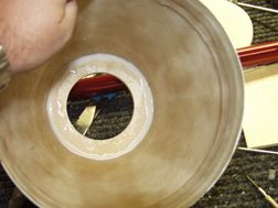
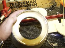
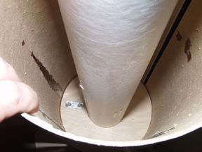
Step 3 - Tail cone Assembly 11/30/2003
The tail cone features heavy fiberglass construction with the aft centering
ring
glued in place with a very heavy pour of Epoxy mixed with micro balloons to
thicken the mixture. A follow up pour of epoxy was used in the exterior end of
the tail cone to seal the motor mount in place. A clear flat area was left for
the attachment of the 98mm Aeropack motor retention system. An 98mm to 75 mm
Aeropack motor adapter will be used to fit the M1315 motor for the attempt.
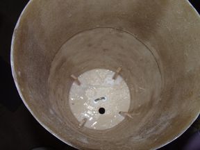
Step 4 - Motor Mount Installation 12/3/2003
 The fore motor mount centering ring is
epoxied in place in the 4-fin can body tube using 30 min epoxy. Before
installation, the entire length of the motor mount tube was roughed up with 120
grit sandpaper to assure good adhesion or the fins to the motor mount tube.
Once dry, a reinforcing pour is done from above to solidify the connection.
The fore motor mount centering ring is
epoxied in place in the 4-fin can body tube using 30 min epoxy. Before
installation, the entire length of the motor mount tube was roughed up with 120
grit sandpaper to assure good adhesion or the fins to the motor mount tube.
Once dry, a reinforcing pour is done from above to solidify the connection.
To maintain alignment the internal motor mount the middle centering ring is slid onto the motor tube at the aft end of the body tube/fin canister with no glue.
 This deviates from the instructions provided
by Polecat and once this ring is removed, will allow internal visual
inspection and reinforcement of fin attachment to the motor tube if deemed
necessary.
This deviates from the instructions provided
by Polecat and once this ring is removed, will allow internal visual
inspection and reinforcement of fin attachment to the motor tube if deemed
necessary.
Step 5 - Installation of guide fins and bulkhead into nosecone 12/3/2003
The nosecone bulkhead with 1/4" harness u-bolt installed is epoxied into the nosecone and glued in place with multiple pours of epoxy mixed with micro balloons to thicken the mixture and to fill gaps.
 At the same time the 4 birch guide fins are
taped in place to assure proper alignment and are glued in place during the
same pours indicated above. Thick fillets of epoxy are done on all
internal connection points of the fins to the nosecone assembly and bulkhead.
The nosecone assembly is set aside to cure completely. A hole is left in the
nosecone bulkhead to add nose weight later in the construction process.
At the same time the 4 birch guide fins are
taped in place to assure proper alignment and are glued in place during the
same pours indicated above. Thick fillets of epoxy are done on all
internal connection points of the fins to the nosecone assembly and bulkhead.
The nosecone assembly is set aside to cure completely. A hole is left in the
nosecone bulkhead to add nose weight later in the construction process.
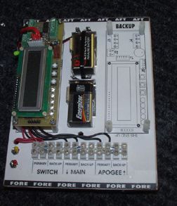
Step 6 - The electronics sled for the electronics bay is assembled and populated with redundant electronics, redundant battery holders and connectors 12/3/2003
The electronics and schematic are installed to the 6" x 8" electronics board and the slides are then glued to the board clamped to dry.

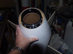
Step 7 - Epoxy in forward bulkhead and coupler for electronics bay
12/4/03
The fore bulkhead was epoxied in place 3" inside the upper section of body tube. To assure proper alignment, the 9" coupler was glued in at the same time. A reinforcing pour of epoxy was made to the top of the body tube onto the fore bulkhead. Care was taken not to get any epoxy onto the charge holder cups or charge wiring pass through.
A 7/8" hole was bored through the side of the coupler 1 1/2 inch below the fore bulkhead (inside the bay) to install the single throw, double pole NEMA switch for external arming of the electronics. The electronics slide was installed and the removable bulkhead was installed to assure a proper fit and seal.
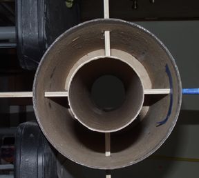 Step 8 - Fin Can/Booster - Fin
Attachment
Step 8 - Fin Can/Booster - Fin
Attachment
All fin slots are sanded to assure a smooth dry fit of the 4 birch fins through the body tube fin slots and through to the motor tube. A laser level is used to project a true 90 degree parallel line up the sweep of the fin assuring an exact positioning of the the fins once epoxied to 90 degrees relative to each other.
Epoxy is applied to each fin root and to the upper edge (to glue to the upper centering ring) and each fin is attached to the motor tube. Accurate measurements are made between each fin to assure the laser system worked (which it did perfectly!) Once dry, the fin roots to the motor tube, the upper centering ring and inside the fin slot on the body tube are reinforced with epoxy fillets for additional strength.
NOTE: 2 part foam will not be used as the rocket is very bottom heavy to begin with.
The Lower centering ring for the body tube is not glued in place pending TAP review as the area will be concealed once attached.
(12/7/03 - received approval from Mark Clark TAP to proceed)
Once all the internal fins to motor tube and inner wall of the body tube has been reinforced with fillets of epoxy mixed with micro balloons, the aft centering ring is glued to the fin base, motor tube and the body tube. An fillet of epoxy is completed on the other side (aft) to the body tube and around the protruding motor tube.
 The boat tail is then
affixed to the end of fin can with a generous pour of epoxy around the base and
where the motor tube passed through the final centering ring at the base of the
boat tail.
The boat tail is then
affixed to the end of fin can with a generous pour of epoxy around the base and
where the motor tube passed through the final centering ring at the base of the
boat tail.
1/8 " SS socket bolts will be added later to further secure the boat tail to the body tube and for visual effect.
The motor tube is then cut flush to the aft centering ring to accommodate the Aero Pack 98 mm motor retainer. The Aero Pack retainer is installed as per enclosed directions.
This concludes the construction of the booster assembly.
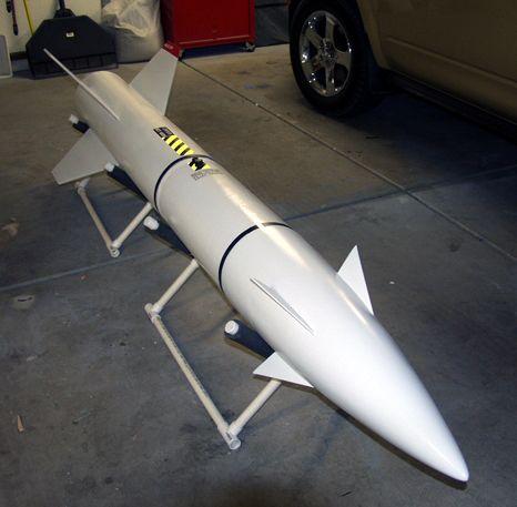 Step 9 - Finishing and final
construction notes
Step 9 - Finishing and final
construction notes
All parachute harness/shock cords are constructed using 5/8"
Quicklinks,
1" tubular nylon with 4 wrap slipknots and epoxy reinforcement at knot
junctions. Additionally tie wraps are used to stop fraying of ends.
Both the aft shockcord (20') and the fore shockcord (10') have 3' Nomex® sleeves over the shockcord at the end exposed to hot ejection gases, furthermore both shockcords are fitted with Nomex® blankets to wrap the parachutes in for protection. All parachutes will attach with 1/4 in quicklinks.
The entire rocket is now assembled and (2 - 1500 series rail buttons are attached with the aft button attached to the fin can 6" above the boat tail into the aft body tube centering ring. The fore rail button is attached with internal reinforcement (Epoxy set) at 5" above the upper MM centering ring.
20 lbs of lead shot is added to the apex of the nose cone for nose weight and held in place with a heavy pour of of West Systems epoxy. This amount was determined by RockSim and a physical balance of the rocket with simulated weight for the loaded motor on the aft end.
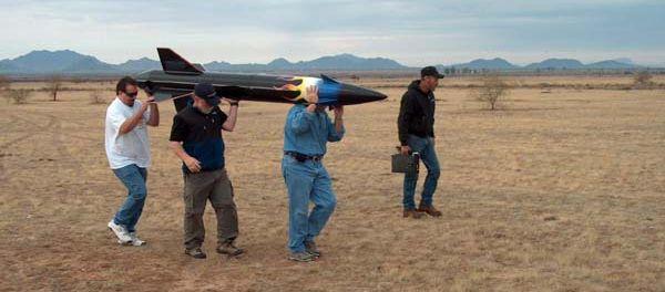
 SUCCESSFUL LEVEL 3 FLIGHT!
January 24, 2003
MWP1
Rocket - 10" Polecat Bull Pup
Weight - 58 lbs
Motor - 98mm Aerotech M1315
Altitude - 3,440’
After watching the weather all week and then driving through light rain this morning to the Rainbow Valley launch site, things were looking a little grim as to if I was going to be able to launch today.
After going through my check list and assembling the AT M1315 motor for the flight, wiring the ejection charges, the breeze that was blowing suddenly died out. Wind was my biggest worry for the flight as the rocket is heavy and with the 20 lb's of nose weight, might weathercock off the rail with a stiff gust on the nose.
Special thanks to Ken Sparks for the ongoing advise and the use of his monster 18' 1500 series rail! We loaded the beast with a little brute force onto the rail, elevated it, armed the dual FC-877's and then loaded and connected the igniter to my ProLaunch long range wireless launch controller and headed back to the flight line.
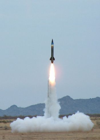
After a 5 second countdown and my mind wishing I was anywhere else at that moment, I hit the launch button and the beast fired up! Now if anyone tells you that a Bull Pup can't fly straight, this flight ends that argument once and for all!
 The rocket cleared
the rail with a wicked tail of flame and went slowly straight up! Not a single
rotation of the airframe... I mean straight!!!! It was textbook perfect.
The rocket cleared
the rail with a wicked tail of flame and went slowly straight up! Not a single
rotation of the airframe... I mean straight!!!! It was textbook perfect.
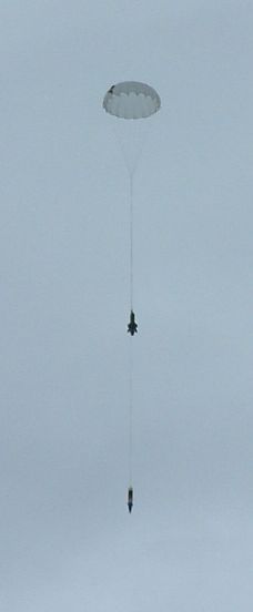
A beautiful arc at the top and perfect timing and deployment by the FC-877's, with a boom from the backup charge 2 seconds later... 14 grams of BP in each charge holder makes a pretty big boom.
My buddies at Trailer Trash Aerospace (Kevin, Marty and Jim)helped me out big time in packing the 17 foot parachute for the flight. Even with 60 ft of 1/2 inch Kevlar® leash, the rocket was under perfect canopy seconds after the charges fired and landed less than 1/4 mile from the flight line, A little scuffed paint, but otherwise ready to fly again.
Now for the special thanks (in no specific order)
Thanks you Mark Saunders (BSD Rocketry) for loaning me the AT case for the flight! Mark, your the man!
Thanks to my buddy, Ken Sparks (SSS Member at Large) for calming me down on several occasions, for loaning me the use of his most excellent rail and most important of all for the great cigar after the fat lady sang! Thanks buddy, your the best!
And finally to my good friends at Trailer Trash Aerospace. Your help (and harassment) with this project were invaluable in the success of the flight and specifically Marty and Keven who put disaster scenarios in my head too many times to count and made me lose sleep worrying about it many nights...
L3 was a blast!!!!
 |
 |
R.W.W. (October 17, 2005)
|
|
M.D. (June 2, 2004)