| Construction Rating: | starstarstarstarstar_border |
| Flight Rating: | starstarstarstarstar |
| Overall Rating: | starstarstarstarstar_border |
| Published: | 2010-05-10 |
| Length: | 19.75 inches |
| Manufacturer: | Dr. Zooch  |
| Skill Level: | 3 |
| Style: | Scale |
 Brief:
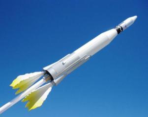
A semi-scale version of the Atlas Agena. Flame fins are added for flight.
Construction:
Picture does not show the three sheets of 3/32" x 3" x 6" balsa supplied in the kit.
Opening the box looked to be typical of a Dr. Zooch kit- Good quality parts. All the instructions and cardstock wrap sheet were rolled inside the T-60 (BT-60) body tube.
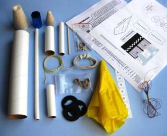 A few unusual pieces were the pre-weighted balsa adapter. Dr. Zooch uses a two ply Kevlar “ribbon”. Not the usual Kevlar you’d find in a rocket kit.
A 10" length of T-3 tubing is included.
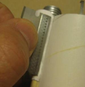
Number 3 on the parts list says: 4 CR25P centering rings. They are actually CR35P rings. I’ve never seen centering rings this small in a kit before.
The corrugated mylar is interesting. It is thin and metallic blue.
I dry ironed the instructions and wrap sheet flat. The cardstock wrap sheet was sprayed with a Krylon clear coat for protection against smearing and dirt.
With the Zooch kits (or any kits with wraps) I always scan the wrap sheets just in case I need to print off another copy. It’s me, I’m very picky about wraps and such. If it doesn’t turn out right the first time, I’ll print and make another. This is the first Zooch kit I’ve built that just had one, single cardstock wrap sheet.
MAKING THE ENGINE MOUNT
The upper and lower CR-MOD templates are cut from the wrap sheet. I didn’t see any reason to cut out the centers, I did cut out the engine hook allowance and index notches.
I also didn’t cut out the two outer semi-circles yet. I thought it would be easier to cut them out after being glued to the centering rings.
 Instead of glueing the templates permanently in place with white glue, I used spray adhesive and removed them after cutting out the semi-circles.
The rounded engine hook notch doesn’t quite match up with the template. I centered everything from the back of the rings.
The semi-circles take time to cut through. I didn’t cut a pie-shaped notch at the index marks, I simply cut a single line straight down to the depth shown.
The templates were removed and the rings marked upper and lower.
In order to clean up the cut semi-circles, I wrapped 400 grit sandpaper around the white barrel side of a Sharpie pen. The Sharpie pen is slightly smaller in diameter than the T-5 tube the circles will fit. I usually contour sand with something smaller in diameter as the sandpaper thickness will bring it up to the correct finished diameter.
I “double-glued” the end of the engine bell strings to the ends of the T-20 tubing to prepare for winding.
I’ll dry wrap the strings to the 3/8" mark to get an idea of the spacing of the windings. On one test wrap I did it dry and held the end down with tape. I spread the string wraps as even as I could and used it for a spacing model for gluing on the second tube.
The strings were lightly coated with white glue for just a few inches. The glued area was wrapped and more glue is added to the next few inches. I continued up until reaching the end.
I decided not to use super glue over the thread bands as it could leave bumps and roughness between the wraps. Instead I coated white glue overall the thread rows at once and smoothed out the glue with a finger.
The centering rings are lined up with the index line drawn earlier. Just to be safe, I set the “spoof” engine tubes in their semi-circle cutouts to be sure all lined up. The rings were tacked in place with small drops of thin CA. I followed with white glue fillets.
I decided to install the engine hook before gluing on the spoof tubes. This way I could add the tape wrap without the tubes getting in the way.
I’ll paint the spoof engine tubes with Walmart spray aluminum before gluing in place on the central engine tube. I’ve had great results with their inexpensive aluminum before.
I filled the seams in the spoof body tubes with Elmer’s Wood Filler.
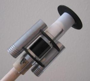
Once again, Zooch uses a reinforcement band directly below the top of the engine hook. It’s a smart addition on the thin T-20 tube. This eliminates any chance (at ejection) of the engine hook pulling and tearing the tube.
The hook was set in it’s slot and a wrap of electrical tape went over it, between the centering rings.
The spoof tubes weren’t glued on yet, so I was able to slide the engine mount in place. I made the marks using the semi-circles I had cut out earlier. This way I knew the cut out slots in the T-60 tube would match up with the spoof tubes.
I set the spoof tube into the semi-circle cutouts with the ends of the thread bands facing towards to the central motor mount tube. I didn’t want the loose ends facing outward, they won’t as easily be seen in the center.
I marked the spoof tubes for masking. The masked areas would keep the gluing surfaces clean.
After a coat of grey primer and sanding , I followed with spray aluminum.
I first set the spoof tubes in their semi-circle cutouts without glue. The spoofs overhang the centering rings by 9/16". After being sure of the overhangs, I applied a small drop of CA to the spoof/centering ring joints to glue in place.
The remaining CR2060F Centering ring is glued to the top of the engine mount assembly. I didn’t glue it flush, but 1/16" down from the top of the motor tube. This was a stronger joint as I could fillet both sides with white glue.
I slid the engine mount assembly into the T-60 tube to check the alignment of the spoof tubes. Before cutting the T-60 tube I wanted to double check the alignment. I made slight adjustments to the pencil lines to fit the final spoof tubes locations.
MAKING THE PODS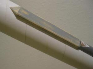
To make the pod covers you laminate two pieces of balsa. One is 4 inches long, the other 2 5/16" long. Both are 9/16" wide.
The instructions have you round the cut tip before sanding to the body tube contour. I would recommend rounding the tip after sanding the inside contour. This way, you don’t round off the tip.
To sand the body contour, I didn’t sand it on the T-60 tube at first. I always start with the next size smaller tubing. In this case a BT-55.
The hardest part of sanding pieces to fit a tube curve is the middle, highest point of the curve. Starting with a smaller tube guarantees there will be enough removed from the middle. When you get it close, switch to a finer grit on the larger body tube you are going to glue in on.
When test fitting the Engine Nacelles, I found them a little wide in the front. No problem, a simple trim. In order to get the paper nacelles to fit better over the top of the spoofs, I sanded off the top of the T-5 tubes down with a sanding block.
As I expected, the Heat Shields required a bit of fitting. Mine ended up being closer to the height in the illustrations. The fit on each model is going to be a little different and would require trimming.
I formed the Engine Nacelle Shrouds in the soft fleshy heel of my hand. I pressed and rolled a dowel over the shroud until it was rounded. The smaller front end of the Nacelle Shroud is more of a rounded square shape.
The smaller heat shield pieces required a bit of sanding to get the shrouds to wrap all the way around and touch the tube.
Before gluing, I drew lines at the center and the intersection of the overhang.
Rather than use a slower drying white glue, I held the heat shields on their pencil lines and touched super glue to the joints. In the end it was a good fit on all sides.
The fairing wall support strips were cut - six pieces, 3/32" x 32" x 1". All were tacked in place with CA.
After test fitting I had to sand the middle support strip down a bit.
I’d already filled the pod covers. I sprayed them off the body with grey primer.
After I was sure of the Nacelle fit, I glued the Pod Covers onto the body. I ran a light coating of White glue on the underside and pressed them into place. I sighted from the rear making sure they were straight.
After holding them tight against the body for a few minutes, I could see some of the edges lifting. I ended up using a small amount of CA on those points, keeping a paper towel handy to pick up any overflow. This seemed to hold them down and would make for easier fillets later.
 I was concerned about gluing on the Nacelles. Even with the supports in place there was a slight bowing of the outer faring walls.
I decided to tack the upper corners of the Nacelles against the pods with small amounts of CA. On the bowed sides of the Nacelles, I held them down with the flat backside of a razor blade. This insured the sides would be straight while I touched CA to the long joint.
If any sanding is needed, the CA would strengthen the paper Nacelles. I also added CA to the back overhang of the Nacelles so they wouldn’t be bent when handling.
MAKING THE FLAME FINS
I jumped ahead to the Flame Fins. Being the fins are supposed to be a flame profile, the fins outside edges shouldn’t necessarily be cut the same. But, the root edge, width and length should match the pattern.
I used 400 grit sandpaper wrapped around the white back end of a Sharpie pen to sand the small curves in the outside edges. The pen barrel kept everything squared up. I won’t bother trying to round the edges of the fins.
After I glued the small CR35P Centering Rings to the T-3 Tube, I set the root edge of the fins against the T-3 tube.
While the fins are being filled and sanded, I jumped back to the body details.
I had to find the exact center of the main tube between the Nacelles. A 1/16" paper strip is glued to the body on each side.
The paper strip was cut from cardstock.
To find the center, I pushed a piece of paper into both sides of the Nacelle / body tube joint. I simply folded that length in half and marked the center. That mark was extended up the tube.
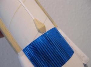 Next, you mark the line 3/8" up from the corrugated wrap.
I started gluing the long strip down at the 9/16" mark. The Vernier Engines were glued on, butted up against the end of the cardstock strip.
BODY DETAILS
The 1/8" dowel is rounded and glued to the body. While the instructions don’t say to sand the dowel to a half-round shape, the illustration shows it. I sanded half off down it’s length and rounded the top. I recessed an area wide enough to fit it over the corrugated wrap.
It would be near to impossible to mask the dowel after it is glued. I’ll paint the rocket white, then mask and paint the aluminum. I’ll glue the dowel on after all is painted.
After much thought, I figured out how to make the thin balsa Nosecone Line Fairing. I usually fill balsa before gluing it to the body. This is a very thin piece and would probably warp when painted with filler.
I decided to make and fill it on the balsa sheet, then cut it off and glue in place. Using my metal sanding block with 220 grit sandpaper I thinned the edge in a long “step”. Making the Fairing this way would help prevent warping. It’s easier to form and round the edge while still on the balsa stock.
The fairing was filled, sanded then cut off the sheet.
The tip of the Pod Cover was cut off and the Fairing glued in line to the top of the body tube. The end was sanded square to the end of the body tube.
The Fairing was continued up the Adapter. I sanded the angle to match the Fairing at the end of the Body Tube.
Finishing:
PAINTING
The rear Centering Rings and Spoof Nozzles were masked off by setting small squares of masking tape against the extended inside wall of the rear main tube. I stuffed scraps of paper towel into the recesses.
The entire model was sprayed with grey primer and sanded. Rustoleum Painter’s Touch Gloss White followed, sanding in between coats. I didn’t want to paint the upper T-50 tube as it was going to get a printed wrap. For painting the upper adapter and nose cone I used some scrap BT-50 and sprayed all as one white unit. I know, it should be flat finish, but flat finishes get dirty easier. I’ll hit it with a dull coat later on.
The Nose Cone was already filled, primed and painted. I drew the line down the upper T-50 tube for the Agena Wrap.
I don’t have much luck using white glue on full body tube wraps. I cut out the wrap and hit it with spray adhesive. The spray adhesive lets me reposition the wrap if necessary. Using White glue, you only have one attempt doing a straight wrap.
Using just spray adhesive the end edges won’t stay down. I lay a small amount of white glue on my knife blade and push it under the raised edge.
Earlier I painted the model Gloss White. I worked over the weekend which gave the paint time to set up.
I masked around the Pod Cover with scotch tape. Masking Tape went over the edges of the Scotch Tape widening the masked areas. I cut up a plastic grocery bag and wrapped tha around the larger areas of the upper body.
The masked areas around the Engine Mount were left on for the Aluminum paint. I’d had good luck with the cheaper WalMart Aluminum before and decided to use it again.
I did my typical process of light coats then a final heavy coat. The WalMart Aluminum dries clear and even.
While Scotch Tape gives me the best masking lines, it can be hard to remove in one piece. It’ll tear quite a bit when removing but the results are worth it.
The upper T-50 Body Tube was glued to the Adapter. Before gluing in place, I used a Sharpie pen to blacked the lower edge of the Body Tube and wrap. This gives a sharper color separation line between the wrap and Adapter section.
FINISHING UP
The 1/8" Dowel was left off during painting. It’d be too hard to mask around it. I sealed, primed, sanded and painted it Aluminum. It was positioned and glued in place over the Corrugated Wrap.
The Launch Lug had the seams filled, then primed with Gray Primer. After sanding it was sprayed White then cut in two. Both pieces were glued in line using a short length of 1/8" dowel to line them up.
 Construction Rating: 4 out of 5
Flight:
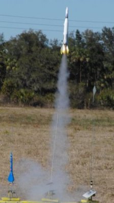
I finally got around to flying The Atlas Agena at the R.O.C.K. monthly launch on April 3, 2010. There was plenty of wind and I was reluctant. I played it safe and went with a Estes B6-4. I had no reason to be worried. Even with wind gusts, the flight was straight up, recovery was fine, no damage.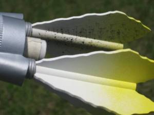
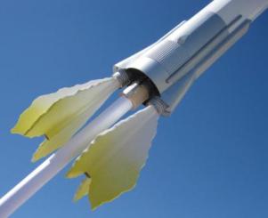
The second flight was on May 1, 2010 at the R.O.C.K. launch. This time with a German made Quest B6-4. The picture shows the crud than was blown out the engine and deposited on the inside fin surfaces. No problem, the residue wiped right off with a damp paper towel.
Considering all the detail and nose weight the rocket gets good altitude on the B6-4.
Recovery:
The enclosed Ribbon style Kevlar is 20" long, tied to the 1/4" wide elastic at 36" long. Total combined Shock Cord and Kevlar (once tied) is 52" long.
Instead of attaching the Parachute at the Screw Eye, I connected it 1/3 the way down the Elastic from the Nose Cone.
 The parachute is 13" wide from flat to flat side. Descent speed is fine with this sized parachute. No burning, damage or wear.
Flight Rating: 5 out of 5
Summary:
Another great build from Dr. Zooch and now a favorite flyer.
Plenty of detail and just enough of a build challenge.
Overall Rating: 4 out of 5
 |
 |