| Construction Rating: | starstarstarstarstar_border |
| Flight Rating: | starstarstar_borderstar_borderstar_border |
| Overall Rating: | starstarstar_borderstar_borderstar_border |
| Published: | 2010-11-13 |
| Manufacturer: | U.S. Rockets  |

Overview
The Tall Tail 10 is a big honkin' single-stage rocket designed to fly on one 24mm or 29mm motor. The basic design is three 3-foot sections of decreasing diameter on the way up, with balsa transitions between each section. The bottom section has three long elliptical fins and the motor mount. Each 3-foot section comes apart for transport. In flight, the rocket breaks into two segments at ejection: the upper 6+ feet with the nose cone, and the lower 3 feet with the fins and motor mount. Each segment recovers on its own 6-foot shock cord and 30-inch mylar parachute.
Kit Specifications (from instruction sheet)
- Length: 118"/2997mm *
- Diameter - 2.25"/57mm
- Weight - 390g
- Skill Level: 1
* The printed spec sheet does not quite match the actual parts in my kit.
Measured Dimensions
- Length: 115.65 inches (24mm motor adapter adds another 0.5 inches)
- Component Weight (no glue or paint): 13.26 oz (29mm mount) 13.61 oz (w/24mm adapter)
Background:
I won this kit a first prize in EMRR Virtual Rocket Contest #6 (Longnecks) in early March. My kit was the first production unit, #001. Due to some component procurement problems, I did not receive the kit until early May. Not a problem, though. Jerry from USR kept me up to date on the status with periodic e-mails.
The kit arrived packed in a standard clear plastic bag with a paper hang tag. No shipping damage. My first reaction: WOW! There's a whole lot of rocket in that bag!

Parts List
- 2 BT-22-18 Airframe Tubes
- 2 BT-60-18 Airframe Tubes
- 2 BT-55-18 Airframe Tubes
- 2 TC-22-2 Tube Couplers
- 1 TC-55-2 Tube Coupler
- 1 NC-55-Parabolic Nose Cone
- 1 BR-22-60 Large Balsa Reducer
- 1 BR-60-55 Small Balsa Reducer
- 2 CR-22-11 Centering Rings
- 1 BT-11-4 Motor Tube
- 1 CT-11-9-2 Conversion Tube
- 1 BT-9-3 Motor Tube
- 3 Sheets 3"x9"x3/32" Balsa Fin Stock
- 1 Elliptical Fin Pattern
- 1 SE-1 Screw Eye
- 1 SA-1 Screw Eye Anchor
- 1 LL-1/4-2 Launch Lug
- 2 SC-7 Shock Cord
- 1 SCM-1 Shock Cord Mount
- 2 PAR-30 Parachutes
- 1 Tall Tail 10 Instructions
- 1 Report: "Motor Installation"
The largest tubes are similar to Estes BT-70 but twice the thickness. They have a smooth white glassine finish with minimal spiral. The other tubing looks like standard brown BT-60 and BT-50.

I was disappointed to see that the big tubes had suffered some obvious water damage before they were packed into the bag. The tubing had swelled enough that the couplers would not fit, and the tubes smelled of mildew. I ended up trimming off 1.5 inches from each large tube.
The large tube couplers are not standard brown kraft paper; they have the same white glassine coating as the large body tubes. The shock cords are a very generous 72 inches long.
The instructions are printed on four 8.5x11-inch pages on orange paper. The directions have lots of text and plenty of computer-generated illustrations.
Construction:
This kit is rated as Skill Level 1, but I think it should be more like Skill Level 2. It's not that the construction is difficult, but flying it successfully will require skills that a beginner is not likely to have.
The first step is to cut the fins from the provided fin stock. These fins have a 3-inch chord, 9-inch semi-span, and 3/32" thickness. I was a bit concerned by the amount of flex in the fins when I cut them out. Flight testing would later validate my concerns. The fins are surface-glued to the bottom-most large body tube. The launch lug is cut into two pieces and glued onto each end of that same tube.

Next, an adapter is built to allow using 24mm motors in the 29mm native motor mount.
") The balsa transition section that couples the middle section to the bottom has an interesting layout. A plywood reinforcement disk is glued to the bottom of the transition. The screw eye is inserted through this disk into the balsa. The result is very strong without adding a lot of weight. Next a 2-inch length of tubing coupler is glued to the bottom of the transition. When questioned about the reason for this, Jerry at USR informed me that this was added to prevent flexing of the body. I can attest that it works quite well at preventing the flexing that is common in SuperRoc designs.
The balsa transition section that couples the middle section to the bottom has an interesting layout. A plywood reinforcement disk is glued to the bottom of the transition. The screw eye is inserted through this disk into the balsa. The result is very strong without adding a lot of weight. Next a 2-inch length of tubing coupler is glued to the bottom of the transition. When questioned about the reason for this, Jerry at USR informed me that this was added to prevent flexing of the body. I can attest that it works quite well at preventing the flexing that is common in SuperRoc designs.
All three pairs of matching 18-inch tubing are glued together using couplers. The top two 3-foot sections each have a balsa transition glued to its bottom. The nose cone is friction-fit into the top of the upper section.
One shock cord is glued into the lowest section using a paper shock cord mount. The other shock cord is tied to the screw eye in the base of the largest transition. Parachutes are tied to each shock cord.
Finally, the 29mm motor mount is assembled and glued into the bottom of the large tube.
Modifications
Okay, that was a description of how the kit was supposed to be built. Now I'll tell how I actually built it.
Fin Braces - I was a bit concerned about such a thin gluing surface for such a large fin, so I decided to experiment by making fin braces from 1/4" balsa angle stock. First I glued the angle stock near the root edge of the fin. Then I wrapped a piece of sandpaper around the tube and sanded the root to match the contour of the body. They turned out okay, but it was a tedious process to get them shaped without having them off-center or crooked, and I don't necessarily recommend others attempt this.
") |
") |
After painting the fins and body, I glued the finished fin assembly to the body using 5-minute epoxy. The mating surfaces were masked off during painting so that the epoxy could grip bare wood and tubing. The masking tape shown in the photo below was just an aid for getting the vertical alignment consistent.

Weight Reduction - I was very concerned about the weight of this rocket. Even with minimal paint or glue, this kit comes in right around the FAA weight limit of 16 ounces when loaded with an E9 or an F21. Even with no paint at all, the takeoff weight would exceed the rated Maximum Liftoff Weight for an Estes E9 or D12 engine. I started looking for places to shave weight.
- Since my tubing had some water damage, I cut 1.5 inches from each BT-70 tube. Net savings: 0.37 oz.
- The twin 30-inch mylar parachutes are way too big for this kit. Swapping them down for 21-inch mylar chutes reduces the drift and saves 0.49 oz.
- The SE-1 screw eye provided is the same one that is used in USR's much larger kits. There is not much stress on it during deployment, so a smaller SE-0 screw eye is easily strong enough and weighs 0.13 oz less.
Total savings so far: 0.99 oz. That got me under the FAA limit, but it was still marginal for use with E9 or D12 engines.
Modularization - I noticed that if I did not glue the coupler to both pieces of tubing in the middle of each 3-foot section, I would be able to add or remove segments at will. By removing one 18-inch piece of heavy tubing from the bottom section, I could save about 2.5 ounces. That would get me well into the safe weight range for a D12 or E9, while still being a respectable 8+ feet tall. By removing additional tubing segments, shorter configurations of 6.5 and 5 feet tall are also possible.

As an added bonus, the disassembled 18-inch pieces can nest together, making it possible to put the entire rocket back into its original bag with just the fins hanging out. This makes transport very convenient.

Interchangeable Motor Mounts - After reading about the USR Interroc with its modular "Interchangeable Motor Mounts-TM", I thought this would be a slick addition that would allow me to choose either a single 24mm, single 29mm, or 3x24mm cluster. I used the Tall Tail 10 kit parts to make a removable 29mm mount, and Jerry kindly sent me the extra parts to make a 3x24mm mount.
") |
") |
") |
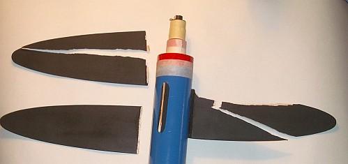
Jerry is a firm believer in the use of masking tape for thrust rings and motor retention. I find that tape has its uses, but I prefer other methods when they are available. For that reason, I used strips of the water-damaged tubing to make thrust rings on the outside of each interchangeable mount (painted red in the photos above and below).
") |
") |
I also added a threaded rod with T-nuts on each end to retain the motors in the cluster mount. The threaded rod is long enough to hold E motors. It retracts into the body when flying D motors so that there is not a hot metal spike sticking out of the bottom during landings.
I will still be using tape to hold the mounts into the airframe, but not as much.
Finishing:
") Because I was concerned about the weight, I skipped my usual routine of spiral filling, priming, and sanding. Instead, I went straight to the final finish colors: Apple Red Gloss for the top section, White Gloss for the middle, and Brilliant Blue Gloss on the bottom. One coat of white was not enough to cover the brown kraft tubing so I added a second coat of white paint on the middle section. The nose cone got a coat of Flat Black. All paints were Rustoleum Painters Choice.
Because I was concerned about the weight, I skipped my usual routine of spiral filling, priming, and sanding. Instead, I went straight to the final finish colors: Apple Red Gloss for the top section, White Gloss for the middle, and Brilliant Blue Gloss on the bottom. One coat of white was not enough to cover the brown kraft tubing so I added a second coat of white paint on the middle section. The nose cone got a coat of Flat Black. All paints were Rustoleum Painters Choice.
The fins got one coat of Kilz Primer, sanded down to almost bare wood, then a coat of Flat Black. The balsa transitions also got a coat of Kilz Primer mostly sanded off, and a coat of Red or Blue.
The kit comes without any decals. To jazz things up, I took a leftover US Rockets logo sticker from a USR MR-2B kit I was building and put it on the blue bottom section. To make the decal colors show up better, I added a small square of white paint where the decal would go.
I stuck some patriotic window clings on the white middle section. I intended to use Future acrylic floor polish to bond them in place, but after three flights none of them has peeled off yet.
Construction Rating: 4 out of 5
Flight/Recovery
Recommended Motors
| 24mm | 29mm |
|---|---|
| D12-3 E9-2* E25-4* F21-4 F25-4* G35-4 D12-0+D12-3 |
USR:
E10-4*E20-4* F20-4* F40-4* G30-4* G60-4* H60-4* |
The instructions list many recommended motors that are no longer available.
The instructions show predicted altitudes for some motors, but most of the predictions are too high. Below are some altitude predictions using the measured weights. The first table also includes recommended rod lengths to reach 30 MPH safe flight speed.
In most of these tables, I recommend AGAINST flying with single Estes motors because of the slow takeoff speed. Out of fairness to Jerry, low performance flights were exactly what he intended when he designed this kit. He even makes light of it on the Tall Tail 10 web page, changing his company motto to "LESS Power To You!" Your mama needs more drama, and drama is what you'll get launching it with a single Estes engine.
| Engine |
Max Alt
(feet) |
Optimal Delay (seconds) |
Recommended Rod Length (feet) |
| D12-3* |
143 |
2.09 |
16.3 ! |
| E9-4* |
278 |
2.61 |
26.3 ! |
| E15-4 |
658 |
4.26 |
6.8 |
| E30-4 |
685 |
4.58 |
3.2 |
| F21-6W |
997 |
5.35 |
4.1 |
| F23-4FJ |
939 |
5.37 |
4.0 |
| G35-7EJ |
1834 |
6.72 |
2.6 |
| G38-7FJ |
1592 |
6.69 |
3.6 |
* Single Estes engines not recommended unless very calm wind
| Engine |
Max Alt (feet) |
Optimal Delay (seconds) |
Configuration |
| D12-3* |
156 |
2.21 |
9.5-foot 24mm |
| E9-4* |
305 |
2.80 |
9.5-foot 24mm |
| E30-4T |
749 |
4.80 |
9.5-foot 24mm |
| F21-6W |
1108 |
6.83 |
9.5-foot 24mm |
| 3xD12-5 |
911 |
5.68 |
9.5-foot Cluster |
| 3xE9-6 |
1562 |
6.69 |
9.5-foot Cluster |
| F23-4FJ | 1043 |
5.80 |
9.5-foot 29mm |
| G38-7FJ | 1749 |
7.18 |
9.5-foot 29mm |
* Single Estes engines not recommended unless very light wind
| Engine |
Max Alt (feet) |
Optimal Delay (seconds) |
Configuration |
| D12-3* |
247 |
2.94 |
8-foot 24mm |
| E9-4* |
492 |
3.79 |
8-foot 24mm |
| E30-4T |
933 |
4.80 |
8-foot 24mm |
| 3xD12-5 |
1123 |
6.58 |
8-foot Cluster |
| 3xE9-6 |
1870 |
7.53 |
8-foot Cluster |
| F23-4FJ | 1301 |
6.38 |
8-foot 29mm |
| G38-7FJ |
2007 |
7.41 |
8-foot 29mm |
| D12-0 + D12-3* |
646 |
4.31 |
8-foot 24mm CHAD staging |
* Single Estes engines not recommended unless light wind
| Engine |
Max Alt (feet) |
Optimal Delay (seconds) |
Configuration |
| D12-3 |
304 |
3.32 |
6.5-foot 24mm |
| E9-4 |
600 |
4.05 |
6.5-foot 24mm |
| 3xC11-5 |
556 |
5.12 |
6.5-foot Cluster |
| 3xD12-7 |
1291 |
6.94 |
6.5-foot Cluster |
| 3xE9-8 |
2039 |
7.82 |
6.5-foot Cluster |
| D12-0 + D12-5* |
781 | 4.81 | 6.5-foot 24mm CHAD staging |
* Single Estes engines not recommended unless light wind
| Engine |
Max Alt (feet) |
Optimal Delay (seconds) |
Configuration |
| D12-3 |
363 |
3.67 |
5-foot 24mm |
| E9-4 |
700 |
4.64 |
5-foot 24mm |
| 3xC11-5 |
629 |
5.37+ |
5-foot Cluster |
| 3xD12-7 | 1421 |
7.23+ |
5-foot Cluster |
| 3xE9-8 |
2185 |
8.05+ |
5-foot Cluster |
| D12-0 + D12-5 |
904 |
5.20 |
5-foot 24mm CHAD staging |
Flight Preparation
 Here are the steps for flight preparation:
- Wrap a band of tape around the base of the engine to form a thrust ring.
- Insert motor into interchange mount.
- Wrap a layer of tape over the joint.
- Insert the interchange mount into the body.
- Wrap a layer of tape over the joint.
- Insert a 2-inch layer of wadding into the lower body tube.
- Fold and insert the TOP parachute into the lower body tube, along with its shock cord.
- Fold and insert the BOTTOM parachute into the lower body tube. This order is important to ensure that both chutes get pulled free in case of weak ejection charges.
- Connect all the remaining sections. Masking tape should be applied to the couplers to get good snug fits at every joint except the one with the shock cord anchors. That one should be able to slide out freely.
Test Flights
Flight 1
The debut of the Tall Tail 10 was at a Cub Scout launch in June. After all the boys had flown their rockets the first time and while they were prepping for their second flight, I quietly slipped the TT10 out of its bag and began assembling the parts. When I held it up and said "Hey guys, do you think I should fly this one?", you should have seen the looks on their faces! They totally freaked out at how big it was and began asking all kinds of questions about it. Even the parents gathered around to get a closer look at it!
I loaded an Aerotech E30-4, figuring that should have enough oomph to get it up to safe flying speed right off the rod, but still keep the flight low enough to stay in the field. As expected, it zipped off the rod quickly, wiggled just a little, then climbed straight and smooth until just before engine burnout. All of sudden, all 3 fins shredded! The airframe lurched around the sky for a few seconds until both chutes opened. As a cloud of balsa confetti rained down on the field, the huge 30-inch chutes carried the body sections gracefully away, far beyond the edge of the field in the nearly-still air.
Post-flight inspection showed that the fin braces did their job. They were still firmly attached, but the fins had splintered. Suspecting that the cause was fin vibration, I put out a plea for help on The Rocketry Forum. My plea was answered by rocket simulation wizard Bruce S. Levison. Bruce used AeroFinSim to analyze the fins and confirmed that an E30 will reach speeds fast enough to shred the long thin fins. Note that E30 is one of the smallest engines that can safely launch this model. It is supposed to be capable of using small H engines. Obviously not.
When I sent an e-mail to Jerry telling him that I had found "the speed of balsa", he good-naturedly congratulated me on the dubious accomplishment. He also asked for suggestions on how to change the fin design to make it safe.
Bruce and I spent many hours over the next few days simulating alternative fin configurations. We determined that shortening the semi-span from 9 inches down to 6-inchs and using thicker 1/8" stock would allow the fins to survive any single 24mm composite engine or any 3x black-powder cluster. Some 29mm engines could still shred the 6"x1/8" fins, but increasing the thickness to 3/16" should allow them to survive most 29mm engines (assuming the glue joints hold). Jerry is looking at making this change in later production kits.
I didn't plan using an H in mine and I wanted to re-use the fin braces that were still attached to the body, so I created a new set of shorter fins using some new 3/32" fin stock. The new fins were only 4.5 inches long, with a reverse clipped delta planform like the USR Transformer. RockSim said that despite having only half the area of the originals, they would still be stable even with clustered engines. According to FinSim, these short thin fins should be able to handle a single F engine or a D cluster easily. A cluster of E9's or a single G may be still be enough to damage those fins. If I was starting from scratch I would have used thicker stock and avoided the risk.
Flights 2 and 3
 About 3 weeks later, I flew at a high-power field in Wisconsin. We had FAA waivers in place, so I assembled the full 9.5-foot configuration and loaded up the 3x24mm cluster adapter with D12-5's. The takeoff weight was about 19 ounces. The wind was blowing about 8-10 MPH, and we had to put sand-bags on the pad to keep it from tipping over. Since the pieces had drifted so far on the 30-inch chutes in much calmer air, I replaced them both with new Rockethead 24" mylar chutes.
All three engines lit simultaneously and the TT10 zipped nicely off the pad. I thought it looked straight but one bystander mentioned a wobble during the flight. At apogee around 1000 feet, both chutes opened perfectly and carried the body segments to gentle landings about 2000 feet down-range. The 24-inch parachutes are still too big.
For the third flight, I replaced the chutes with two 21-inch Rockethead mylar chutes and loaded an F21-6W motor into the 24mm adapter. Takeoff was fast, followed by a nice straight flight. Ejection occured somewhere near apogee. The shock cord from the upper segment got wrapped around the chute for the lower segment, preventing it from inflating. Both segments came down together supported by a single 21-inch chute. The landing was a bit fast, but caused no damage. It looks like twin 21-inch chutes would be about the right size.
Even though other rockets were flying on H and I motors that day, the Tall Tail 10 was the tallest rocket at the launch and got a lot of attention.
Flight 1 Rating: 2 out of 5
Flight 2 & 3 Rating: 4 out of 5
Summary of Suggested Modifications
| Modification |
Pros/Cons |
Recommended? |
| Use narrower span and thicker stock for fins. |
+ Prevents shredding in flight. |
REQUIRED |
| Create balsa fillets to anchor fins. |
+ Makes fin attachments stronger. - Adds about 0.25 oz. - Tedious to get shaped properly. |
Nice, but might not be worth the effort. |
| Glue tubing couplers to only one end of each 18-inch tube. Friction-fit other end. |
+ Modularity. Allows flying in 9.5, 8, 6.5, or 5-foot configurations to best match engines and wind conditions. + Ease of transport. Parts can be nested to fit back into original bag. |
Good idea. |
| Build with "Interchangeable Motor Mounts-TM" | +Allows easy switching between 1x29mm, 1x24mm, and 3x24mm motors. - Adds 0.35 to 0.50 oz. |
Good idea. |
| Replace twin 30-inch parachutes with something smaller, like twin 21-inch. |
+ Reduces drift. + Reduces weight by 0.49 oz. |
Very good idea. |
| Use smaller screw eye for upper section. |
+ Saves 0.13 oz. |
Good idea. |

Overall Rating: I have to give this two different scores. When built using the original parts and directions, I can only give it 2 out of 5. The fins shredded in mid-air when using a relatively small engine, which is a definite no-no. It's a little too heavy to fly safely on the recommended black-powder motors, and unless it is flown naked, it will exceed the 16-oz FAA weight limit at takeoff.
Pros (Stock)
- HUGE. A real attention-getter.
- Balsa transitions make it a bit more stylish than many other SuperRocs.
- Very sturdy for its size.
Cons (Stock)
- Flimsy fins shredded in flight using small motor.
- A little too heavy to fly legally without FAA notification.
- A little too heavy to fly safely with Estes engines.
- Twin 30-inch parachutes are way too large.
- Prepping requires plenty of masking tape.
- Parts arrive water damaged.
- For the $69.95 price, I would like it to use "Interchangeable Motor Mounts-TM" like the $39.95 Interroc.
- A set of stickers would be nice
After being modified with shorter stronger fins, modular sections, interchangeable mounts, and smaller chutes, this is a great rocket, worthy of a 4.5 rating at least.
Pros (Modified)
- HUGE. A real attention-getter.
- Several length configurations to match available engines and wind conditions.
- Adaptable to fly on a wide variety of engine configurations.
- Sections nest for easy transport.
- Very sturdy for its size.
Cons (Modified)
- Prepping still requires plenty of masking tape.
After the bad experience on the first flight I could just written a lousy review and moved on. However, I saw that this kit had potential greatness and I'm glad I spent the time to make the modifications. It's a fun rocket to fly. Hopefully, US Rockets will include many of these changes in their production units.
Overall Rating (Stock): 2 out of 5
Overall Rating (Modified): 4.5 out of 5
 |
 |
Flights
|
|
|
|
J.I. (September 16, 2005)