| Construction Rating: | starstarstarstarstar_border |
| Flight Rating: | starstarstarstar_borderstar_border |
| Overall Rating: | starstarstarstarstar_border |
| Manufacturer: | K&S Rockets  |
Brief:
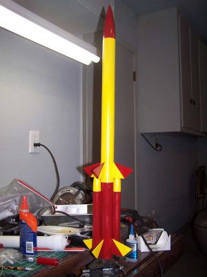
I was snooping around the K&S site and had resolved to place an order and try them out. As I was doing so, I noticed a link for "Special Orders" and had to check it out. The link took me to the Heavy Hitter 4. I knew that this was one I had to try.
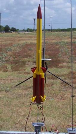
The Heavy Hitter 4 is an interesting rocket in several respects that particularly appeal to me. First off, it is a two stager. I like that. The complexity level goes up again because the booster stage is a cluster composed of 2 18mm "strap ons" and a central 24mm core. The sustainer recovers by streamer but so does the booster. Instead of tumbling, each of the strap-ons ejects a streamer as well.
Construction:
All part were in good condition. The tubes were all pre-marked and each sub-assembly was bagged in a separate plastic bag and labeled for its intended purpose. The fins were precut.
The instructions are pretty basic. They are typed on letter sized sheets. The only illustration is on the first page. All else is text.
The first step is to work on the core motor mount of the booster stage. A longish piece of BT-50 is provided for this purpose, and just in case there is any confusion, it is marked "Motor Tube." The instruction direct that a series of 4 marks be made along the tube. At the third of the marks, a slit is made with a razor knife and the engine hook is inserted. Masking tape is then used to secure the hook in place.
The next step I did not care for too much. A thrust ring is provided which needs to be installed flush with the engine hook. That makes sense but it needs to be installed from the forward end of a tube that is about 10" long. Getting it in involved all sorts of ingenuity and, ultimately, a very long screwdriver. Even as the screwdriver blade was being used to push the thrust ring down into position, the ring wanted to rotate in the BT. Finally, through a combination of pushing on the forward end and just managing to get my ring ringer in far enough on the business end, I was able to get the $@#%$ thing in place but I had no confidence any glue was where it would do any good. I decided to use a long swab and fillet the forward end of the thrust ring after I had the centering rings in place.
There are 3 centering rings, one of which has a notch cut out for the engine hook. These slid into place easily and were glued into place with yellow glue. I decided to let the assembly sit overnight before filleting the opposite side. That garage gets hot even at night in South Texas.
 After letting the glue fillet on the motor mount dry overnight, I went by the shop early the next morning to turn the mount and fillet the other side. That was to leave me free for the evening build session.
The evening build session began with the side booster motor mounts. The motor tube was marked for the hook, a slice was cut and the hook inserted. This was then held in place with masking tape. After the hook was secure, a thrust ring was installed. The motor tube was then marked for the two centering rings and the rings were glued into place. I noticed that all 4 centering rings were tight and needed sanding. In one case, a significant amount of sanding was needed to make the ring fit over the engine hook. When all was assembled, a fillet was applied to the rings and the entire process repeated for the opposite side booster.
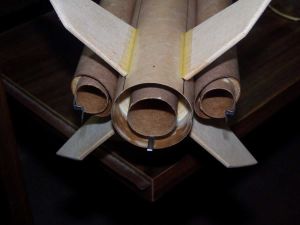
The next step was to put the fins on the central booster. The fins all came precut and were uniform and in good condition. I rounded the leading, trailing and outside edges with sandpaper before proceeding. When I was satisfied with the rounding, I glued them on with CA. The lines for the fins were already marked on the booster. Also marked was a tick mark for the lower edge. This made alignment a breeze. When the CA had set up, I put the booster in an ASP cradle and used yellow glue to begin filleting. I managed to fillet 2 quadrants before I heard the siren song of air conditioning and called it a night.
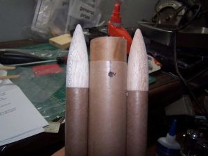
 The next day, being my day off, I went over to the rocket lab a couple of times to tend to the filleting of the fins. Also during the day, I managed to attach the two side boosters. The instructions said to use 5 minute epoxy for this step and that is what I did. A small amount of epoxy was mixed and applied to the line along the length of the side booster. The booster was then put into place on the corresponding line on the central booster. The side boosters have an angled cut at the bottom. The instruction are clear that the angle faces aft. They are also clear that the longer part of the bevel cut is the side that abuts the central booster. What is a bit less clear in the directions is exactly how far forward or aft the side boosters sit. I looked at the photos on the front page and this still remained unclear. I did notice that the lines marked for the side boosters contained tick marks at the same level as those which marked the rearward extent of the fins. I decided to interpret them as such. The process was repeated with the opposite side booster.
Next up, the side booster motor mounts needed to be installed. This was done by swabbing some yellow glue into the body tube, pushing the mount partway in, swabbing in another ring of glue and then shoving it home. The motor mounts are inserted to the point where the aft centering ring is flush with the shorter part of the bevel cut. The instructions also suggest that the engine hooks be aligned outboard. The process was repeated with the opposite side booster and fillets were applied.
Next up came the central motor mount for the booster. This one had three centering rings. I swabbed some glue into the forward end then swabbed in a ring aft. I inserted the motor mount so that the first two rings were in the BT and then swabbed on a third ring. The mount was then shoved home with the end of the motor tube level with the end of the BT and the engine hook centered on one side. This left a significant part of the motor tube extending out the front of the booster. Fillets were applied and the booster was set aside to dry for a while.
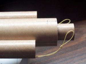
As the booster unit dried, I worked for a while on the booster recovery system. This consists of a streamer deploying from each of the side boosters but nothing in the central one. This did not trouble me. The shock cord mounts did. Both for the booster and the sustainer, Estes style tri-folds are used. There are a few important differences though.
Instead of mounting elastic to the tri-fold, a Kevlarharness is provided. These harnesses consist of a length of Kevlarwith a loop in the middle and the two ends are tucked into the tri-fold. I probably would have modified this system were it not for 2 things. First, I had forgotten about it and already installed the side motor mounts, my preferred point of attachment, and second, I still had not brought my stash of Kevlarto my new rocket works. I decided to give the tri-fold a try.
The two mounts were assembled in the standard fashion and pushed into the side tubes. My intention, once the yellow glue dried completely, was to slather a coating of epoxy on each.
The designed mount also consists of a length of 1/8" sewing elastic tied to a snap swivel at each end. One end snaps to the Kevlarharness and the other to the eye bolt provided pre-installed in the side booster nose cone. A Sky Gripper streamer is then tied into the elastic. The process, of course, repeats on the opposite side.
The glue on the booster unit had yet to sufficiently dry so I turned my attention to the motor mount for the sustainer. This was a simple affair and consisted of cutting a slit in the tube, inserting the engine hook, taping the hook down, installing the thrust ring, installing 2 centering rings and filleting the assembly.
After letting the glue set up for a full day, I next installed the stage coupler. This is a deceptively easy step and can be messed up. The coupler consists of a simple coupling tube that slides into each stage. I found 2 things when trying to slide it into the booster. It was a tight fit to begin with and needed some sanding and that I had been sloppy with the glue while filleting the motor mount. This meant that I had to try and remove the buildup. This was painstakingly accomplished with a razor knife, sandpaper, and a popcicle stick to move the sandpaper in the space between the motor tube and the BT. Finally, I got the coupler to where it fit. The instruction indicate that the coupler should be put in place with 5 minute epoxy and this I did, remembering to mix enough to also coat the tri-fold mounts.
While waiting for the epoxy to set, I installed the sustainer motor mount in the upper BT. This was a simple matter of ringing the tube with glue and shoving it in. The engine hook aligns with the lug line and the bottom of the motor mount goes flush with the bottom of the BT. A fillet was then applied and another build session ended.
After the coupler was safely dry, I proceeded to the next step which was to drill a pair of holes in it to vent gases during staging. The instruction are clear in indicating that the holes are to be drilled not only in the coupler but also in the motor tube itself. This was accomplished with an electric drill. After the holes were drilled, the shavings were trimmed away and the holes were strengthened by wicking some thin and runny CA into them. I then reamed the holes once more with the drill bit sans the drill.
Installing the fins on the sustainer was a simple affair. I rounded them as I had done with the booster and then used CA to affix them to the pre-marked lines. A few hours later, I began to fillet them with yellow glue.
In order to keep myself gainfully occupied while the fillets on the sustainer fins were setting up, I got to work on the recovery system for the sustainer. It was in most respects identical to the ones for the booster. A Kevlar® harness was mounted into a tri-fold and the tri-fold was mounted into the BT. The elastic for this assembly was a bit wider, 1/4" I think, and was again tied to a snap swivel at each end. A 2" Sky Gripper streamer was tied into the system as well.
The HH4 comes with a single 3/16" launch lug. The instructions call for it to be cut in half and for the two halves to be glued onto the provided line on the sustainer. This was done with yellow glue and a short piece of rod to keep the lugs aligned.
When all glue joints seemed to be strong, I decided to test fit the booster and sustainer and found a few problems. The first problem to surface was that the fit over the coupler was extremely tight. I doubt if successful staging would be a real possibility. This was rectified with the copious used of sandpaper thinning down the coupler. In my mind, I removed quite a bit of material but the coupler sill seems to be plenty thick. It might also still be a bit tight. I decided to revisit the issue after priming and painting.
The second problem had to do with the actual fitting of the sustainer onto the length of the coupler. I have no doubt that this was completely and issue having to do with me not the kit, but I found that when the sustainer was on as far as it could be made to go, there was still about 3/8" of coupler showing. I took care of this by firing up the sanding wheel and sanding the length down.
With that done, the nose cone was put into place and the rocket was ready for finishing.
Finishing:
Finishing of the HH4 began with sealing the balsa. Since this rocket was built in a new venue, I found to my disgust that I had not yet brought over any Elmer's sealer. I did find a bottle of old fashioned sanding sealer though and used that. The balsa was in pretty good shape and a total of 3 coats was used with some minor sanding after the final coat. The rocket was then primed with Kilz.
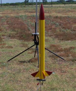
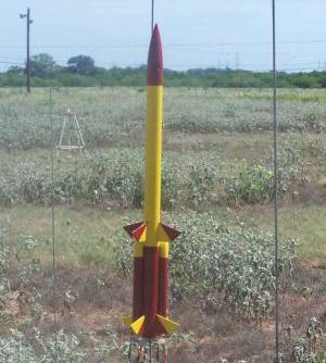
The primed rocket was wet sanded with 320 grit sandpaper and then painted gloss yellow. The plan is to make this a 2 tone rocket with red and yellow.
I decided to do the easy thing with the red. I masked the fins at an angle and covered up the main body of the sustainer. The intention was to give me red triangles on the fins and a red nosecone. It worked.
I have recently sung the praises of Frog masking tape. I used the same tape here but encountered problems of my own making. Recall that I had not used Elmer's filler but sanding sealer. I have not used this in a long while. I apparently needed a few more coats. Paint did leak through some of the "pits" in the balsa. Compared to what I am used to producing, though, it is just fine.
I did the booster unit in the same colors but reversed the prominence. I used mainly red with yellow NCs and fin tips. I had the same problem as before with the bleeding and for the same reason.
I was still having trouble with the tightness of the stage coupler. I sanded and sanded and the thing was still too tight. A tip on TRF helped out. I soaked the coupler with CA to strengthen it and then started sanding again. I quickly realized I was getting nowhere until I remembered my new belt sander. I fired it up and carefully sanded down the coupler, turning it all the while. When it fit well, I reapplied CA and sanded smooth.
My only real wish here is for a few illustrations in the instructions.
Construction Rating: 4 out of 5
Flight:
Flying the HH4 was painful. It was probably the rocket I most looked forward to flying of my recent builds.
I started off conservatively with just the sustainer on a B6-4. It flew well. It would not set any records, but it certainly performed adequately.
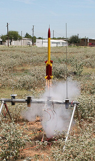
The next flight was with the full rig. Both side boosters were C6-5s. The central booster was a D12-0. In the sustainer, I went with another B6-4.
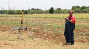
I remembered thinking that this was a heavy rocket as I set it up on the pad. I wish I had done some more thinking along those lines.
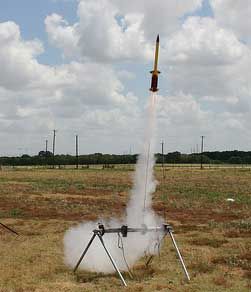
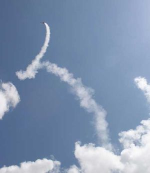
All three of the booster motors ignited and the rocket seemed to fly well for the first 100 feet or so. After that, it whipped around all over the sky scaring the local wildlife and eliciting sarcastic comments from all present. Then staging occurred.
It staged well. The problem was that it was not pointed up when it did so. It was almost horizontal. As it flew pretty straight, gravity took its toll on the rocket and the nose began to dip. It powered into the parking lot of the Alamo Fireworks warehouse. I imagine that warehouse is pretty full right now as they gear up for the 4th.
Before recovering the booster, one theory held that one of the booster motors had not ignited. Inspection revealed that all had. I am convinced that this was a stability problem and that I should have done a swing test and added some weight.
My abysmal performance was due to switching the 18mm motors. I put C's in the side boosters and a B is the sustainer. That tripped the CG.

Recovery:
The streamers on the side boosters deployed fine but tangled just a little bit. The booster was recovered in good shape and will be used for something. I don't know what as yet.

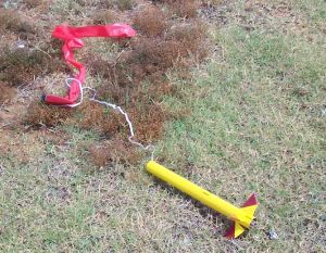
The sustainer streamer deployed fine on the maiden flight but did not get a chance to do so on the second flight. It was probably something to do with impacting the parking lot under thrust.
Flight Rating: 3 out of 5
Summary:
I still like this rocket. I think the problems experience were due to me. I will probably try it again at some point because it is different.
Overall Rating: 4 out of 5
Update 8/9/08:
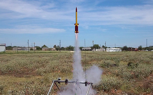
I wrote the review for this rocket and I would like to offer this as an addendum. Well I finally got to try the rebuilt HH4. I decided to try just the sustainer first and loaded up a C6-5. It took off great, ejected at apogee and came down under its streamer. It was time to try the BIG TIME. With that done, it was time to try the full stack. The sustainer had only a B6-4 but the booster had 2 B6-0s and a D12-0. It weathercocked a bit on take off but staged correctly and everything worked, including me. It was a long walk and insecure people who electrify their barbed wire fences should be shot on sight as a public service. I'm happy with this one. (PHOTO CREDIT: RIGHT and BOTTOM Dave Hein)
 |
 |
Flights
|
|
|
|
J.A.L. (June 25, 2008)